Zoom lens and image capture apparatus

Inactive Publication Date: 2007-06-07
SONY CORP
View PDF1 Cites 11 Cited by
  • Summary
  • Abstract
  • Description
  • Claims
  • Application Information

AI Technical Summary

Benefits of technology

[0015] In the zoom lens according to the embodiment of the present invention, the second lens group may have at least one a spherical surface and the a spherical surface has a shape

Problems solved by technology

Since the second lens group of high eccentricity sensitivity is divided into sections one which is constructed as a shift lens group, it is very difficult to avoid an increase in the number of lens elements in the second lens group which is required to decrease the eccentrici

Method used


Image

  • Zoom lens and image capture apparatus
  • Zoom lens and image capture apparatus
  • Zoom lens and image capture apparatus

Examples


first embodiment

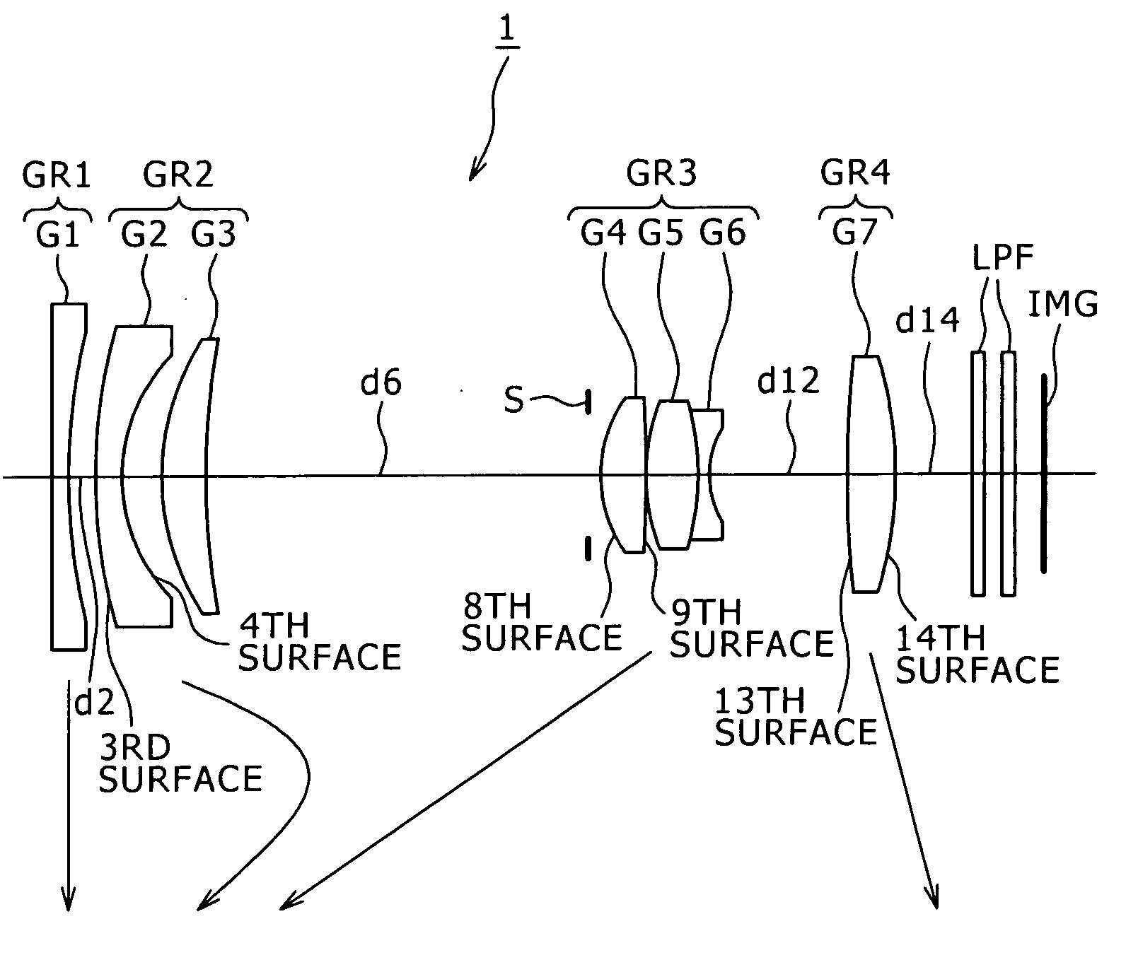
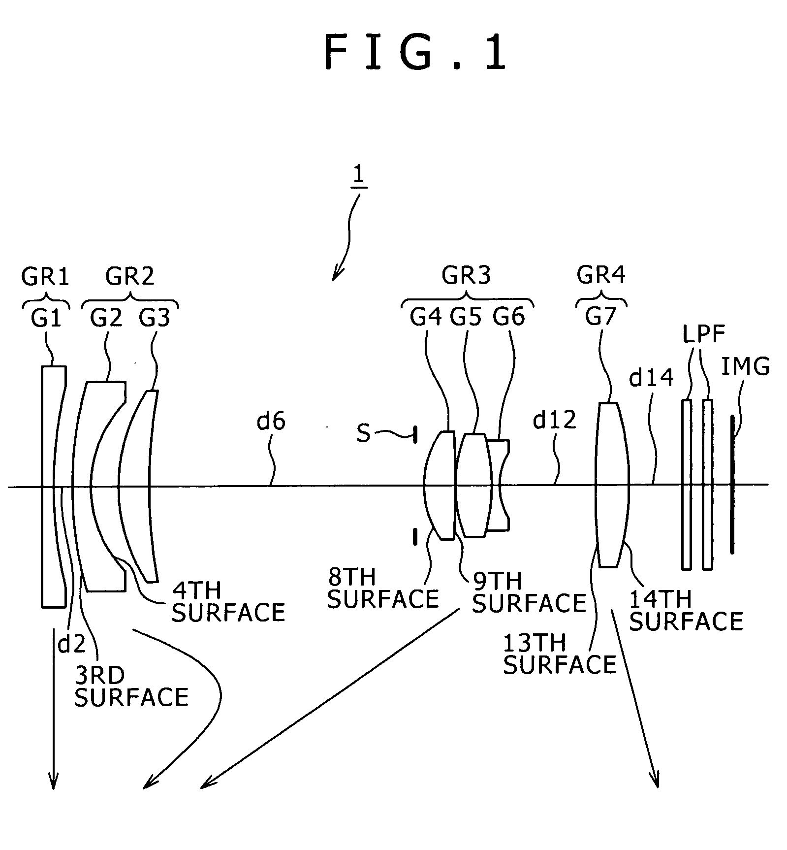
[0050]FIG. 1 is a schematic view showing the lens construction of the zoom lens. A zoom lens 1 includes, in the following order from an object side, a first lens group GR1 having negative refractive power, a second lens group GR2 having negative refractive power, a third lens group GR3 having positive refractive power, and a fourth lens group GR4 having positive refractive power. During the power variation of the zoom lens 1 from its wide-angle end state to its telephoto end state, the first lens group GR1 is fixed, the second lens group GR2 temporarily moves toward an image side and then moves toward the object side, the third lens group GR3 moves toward the object side, and the fourth lens group GR4 moves toward the image side.

[0051] The first lens group GR1 is formed with a single negative lens G1. The second lens group GR2 is formed with a negative lens G2 having aspherical surfaces on both sides and a positive lens G3. The third lens group GR3 is formed with a cemented lens inc...

second embodiment

[0056]FIG. 5 is a schematic view showing the lens construction of the zoom lens. A zoom lens 2 includes, in the following order from an object side, the first lens group GR1 having negative refractive power, the second lens group GR2 having negative refractive power, the third lens group GR3 having positive refractive power, and the fourth lens group GR4 having positive refractive power. During the power variation of the zoom lens 2 from its wide-angle end state to its telephoto end state, the first lens group GR1 and the second lens group GR2 temporarily moves toward an image side and then moves toward the object side, the third lens group GR3 moves toward the object side, and the fourth lens group GR4 moves toward the image side.

[0057] The first lens group GR1 is formed with the single negative lens G1. The second lens group GR2 is formed with the negative lens G2 having aspherical surfaces on both sides and the positive lens G3. The third lens group GR3 is formed with a cemented ...

third embodiment

[0062]FIG. 9 is a schematic view showing the lens construction of the zoom lens. A zoom lens 3 includes, in the following order from an object side, the first lens group GR1 having negative refractive power, the second lens group GR2 having negative refractive power, the third lens group GR3 having positive refractive power, and the fourth lens group GR4 having positive refractive power. During the power variation of the zoom lens 3 from its wide-angle end state to its telephoto end state, the first lens group GR1 and the second lens group GR2 temporarily moves toward an image side and then moves toward the object side, the third lens group GR3 moves toward the object side, and the fourth lens group GR4 moves toward the image side.

[0063] The first lens group GR1 is formed with the single negative lens G1. The second lens group GR2 is formed with the negative lens G2 having aspherical surfaces on both sides and the positive lens G3. The third lens group GR3 is formed with a cemented ...


PUM


Abstract

A zoom lens includes, in the following order from an object side: a first lens group including negative refractive power; a second lens group including negative refractive power; and a third lens group. At least the second and third lens group are movable along an optical axis to perform a zooming action. The second lens group is movable in a direction orthogonal to the optical axis to shift an image in a direction orthogonal to the optical axis. The following (1) and (2) are satisfied:
0.5<(1−βα)×βb<1.0, and  (1)
0.1<|f1/f2|<1.25,   (2)
where βα is magnification of the second lens group at a telephoto end of the zoom lens; βb is magnification of a lens group on an image side relative to the second lens group; f1, f2 are focal lengths of the first, second lens group, respectively.

Description

BACKGROUND OF THE INVENTION 1. Field of the Invention [0001] The present invention relates to a zoom lens and image capture apparatus, and more particularly to a zoom lens having, for example, a camera shake correction function, i.e., the function of correcting shifting of a captured image due to a vibration or movement of a camera, and an image capture apparatus provided with such zoom lens. More specifically, the present invention relates to a zoom lens having a compact and good camera shake correction function suitable for use in an image-capturing optical system for digital input / output device such as digital still cameras and digital video cameras, and to an image capture apparatus provided with such zoom lens. 2. Description of Related Art [0002] In recent years, image capture apparatus using solid-state image capture devices, such as digital cameras, have been spreading. With the spread of such digital still cameras, demand is rising for a far higher image quality, and in the...

Claims


Application Information

Patent Timeline
IPC IPC(8): G02B27/64
CPCG02B15/177G02B15/144513
Inventor IWASAWA, YOSHITO
Owner SONY CORP
Why Eureka
Try Eureka