Dielectric multilayer filter

a multi-layer filter and dichroic filter technology, applied in the field of dielectric multi-layer filters, can solve the problems of narrower reflection band, red-reflective dichroic filter cannot have the required reflection band, ir cut filter or red-reflective filter cannot have the effect of reducing incident angle dependency

Inactive Publication Date: 2007-06-07
MURAKAMI CORP
View PDF1 Cites 38 Cited by
  • Summary
  • Abstract
  • Description
  • Claims
  • Application Information

AI Technical Summary

Benefits of technology

[0027] The dielectric multilayer filter according to the present invention can be configured in such a manner that, in the first dielectric multilayer film, the optical thickness of the films of the second dielectric material is set greater than the optical thickness of the films of the first dielectric material. In this case, compared with the case where the optical thickness of the films of the first dielectric material is set equal to the optical thickness of the films of the second dielectric material, the average refractive index of the entire first dielectric multilayer film can be increased, so that the incident-angle dependency can be reduced. Here, the value of “(the optical thickness of the films of the second dielectric material) / (the optical thickness of the films of the first dielectric material)” can be greater than 1.0 and equal to or smaller than 4.0, for example.

Problems solved by technology

However, since the difference in refractive index between the high-refractive-index films 16 and the low-refractive-index films 14 decreases, the reflection band becomes narrower, and there arises a problem that the IR cut filter or red-reflective dichroic filter cannot have a required reflection band.

Method used


Image

  • Dielectric multilayer filter
  • Dielectric multilayer filter
  • Dielectric multilayer filter

Examples


examples

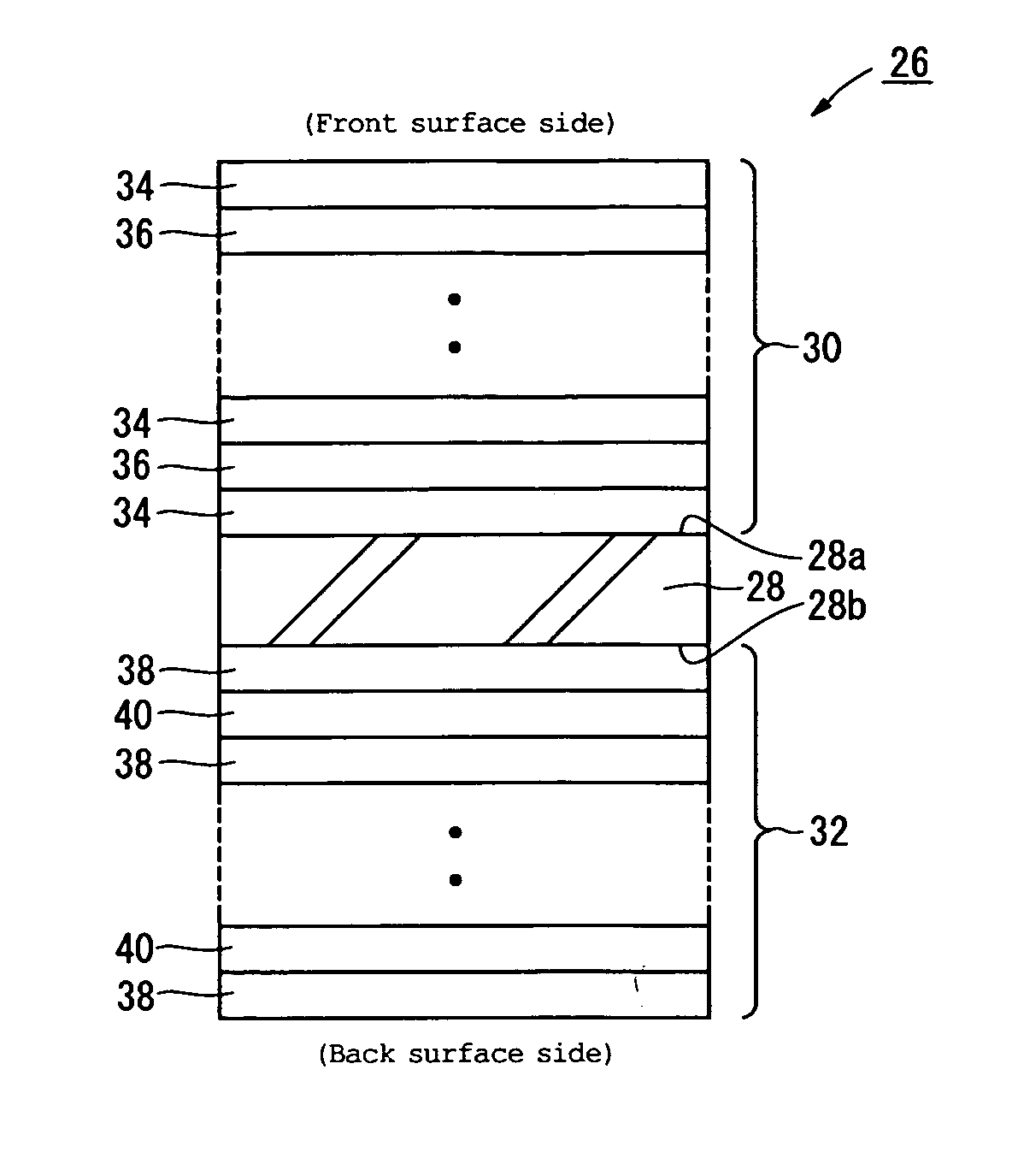
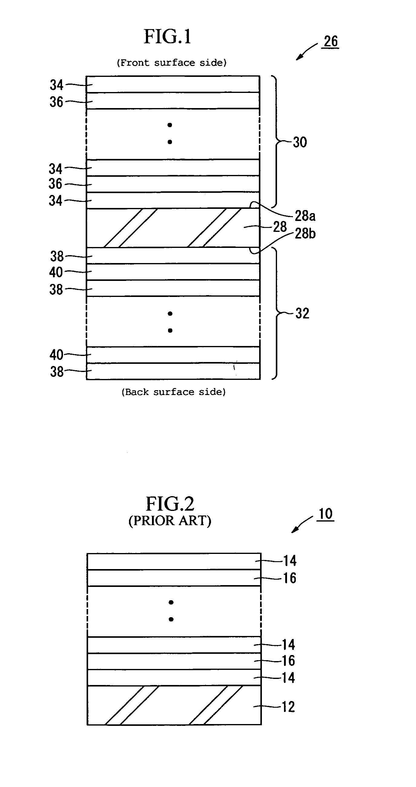
[0071] Examples (1) to (4) in which the dielectric multilayer filter 26 shown in FIG. 1 is configured as an IR cut filter and an example (5) in which the dielectric multilayer filter 26 is configured as a red-reflective dichroic filter will be described. In FIGS. 7 to 30 showing spectral transmittance characteristics for the examples (1) to (3) (all of which are determined by simulation), characteristics A to D represent the transmittances described below. The values of the refractive index and the attenuation coefficient for the design in each example are those with respect to a design wavelength (reference wavelength) λo in the example.

[0072] Characteristic A: transmittance for an incident angle of 0 degrees

[0073] Characteristic B: transmittance of p-polarized light for an incident angle of 25 degrees

[0074] Characteristic C: transmittance of s-polarized light for an incident angle of 25 degrees

[0075] Characteristic D: average transmittance of p-polarized light and s-polarized ...

example

(3)-6

[0227] The IR cut filter 26 was designed using the first dielectric multilayer film 30 and the second dielectric multilayer film 32 according to the following examples.

[0228] First dielectric multilayer film 30: example (1)-5 (average refractive index of the entire stack film=2.17)

[0229] Second dielectric multilayer film 32: example (2)-2 (average refractive index of the entire stack film=1.77)

[0230]FIG. 29 shows spectral transmittance characteristics of the IR cut filter 26 of this design. FIG. 30 is an enlarged view showing the spectral transmittance characteristics within a band of 620 to 690 nm in FIG. 29. According to this design, the following characteristics were obtained.

[0231] High-reflectance band for an incident-angle of 0 degrees: 677.2 to 1011.6 nm

[0232] High-reflectance bandwidth for an incident-angle of 0 degrees: 334.4 nm

[0233] Shift of the half-value wavelength EL at the shorter-wavelength-side edge of the reflection band between the case where the incide...


PUM


Abstract

To provide a dielectric multilayer filter, such as an IR cut filter and a red-reflective dichroic filter, that produces an effect of reducing incident-angle dependency and has a wide reflection band. A first dielectric multilayer film 30 is formed on the front surface of a transparent substrate 28, and a second dielectric multilayer film 32 is formed on the back surface of the transparent substrate 28. The width W1 of the reflection band of the first dielectric multilayer film 30 is set narrower than the width W2 of the reflection band of the second dielectric multilayer film 32. The half-value wavelength E2L of the shorter-wavelength-side edge of the reflection band of the second dielectric multilayer film 32 is set between the half-value wavelength E1L at the shorter-wavelength-side edge and the half-value wavelength E1H at the longer-wavelength-side edge of the reflection band of the first dielectric multilayer film 30.

Description

[0001] The disclosures of Japanese Patent Applications Nos. JP2005-354191 filed on Dec. 7, 2005 and No. JP2006-67250 filed on Mar. 13, 2006 including the specifications, drawings and abstracts are incorporated herein by reference in their entirety. BACKGROUND OF THE INVENTION [0002] 1. Field of the Invention [0003] The present invention relates to a dielectric multilayer filter that produces an effect of reducing incident-angle dependency and has a wide reflection band. [0004] 2. Description of the Related Art [0005] A dielectric multilayer filter is an optical filter that is composed of a stack of a plurality of kinds of thin films made of dielectric materials having different refractive indices and serves to reflect (remove) or transmit a component of a particular wavelength band in incident light taking advantage of light interference. For example, the dielectric multilayer filter is a so-called IR cut filter (infrared cut filter) used in a CCD camera for removing infrared light ...

Claims


Application Information

Patent Timeline
Patent Type & Authority Applications(United States)
IPC IPC(8): G02B1/10
CPCG02B5/0833G02B5/282
Inventor TERADA, YOSHIYUKI
Owner MURAKAMI CORP
Why Eureka
Try Eureka