Nuclear fission fragment kinetic energy rocket engine

a kinetic energy and rocket engine technology, applied in nuclear engineering, nuclear elements, greenhouse gas reduction, etc., can solve the problems of low thrust-to-weight value, solar photon concept, weakening of our sun's energy rays (lower thrust), etc., and achieve high specific impulse

Inactive Publication Date: 2007-06-07
SUTHERLAND DONALD GENE
View PDF16 Cites 8 Cited by
  • Summary
  • Abstract
  • Description
  • Claims
  • Application Information

AI Technical Summary

Benefits of technology

[0015] The fission fragment kinetic energy rocket engine (FKR) is a simple application of the awesome fission process. Neutron bombardment of fissionable material within the engine creates fission fragments, which the invention directly converts into high specific impulse spacecraft propulsion.
[0018] Due to the manageable, low mass feed rate of fissionable fuel utilized, FKR is well suited for low thrust—long-duration missions at continuous full thrust. Because nuclear energy is the most compact form of energy known, and because fission fragments traveling at 4% the speed of light are the highest-velocity mass adaptable to rocket propulsion known, FKR is a quantum leap above other propulsion technologies competing for a lead role in exploration of the outer regions of our solar system and beyond.

Problems solved by technology

No concept yet has gained acceptance by the space community as a baseline for future national or international development.
Although photon concepts offer high Isp, their thrust-to-weight values are extremely low.
An additional limitation of solar photon concepts is the weakening of our sun's energy rays (lower thrust) as distances from the sun increase.

Method used


Image

  • Nuclear fission fragment kinetic energy rocket engine
  • Nuclear fission fragment kinetic energy rocket engine
  • Nuclear fission fragment kinetic energy rocket engine

Examples


Embodiment Construction

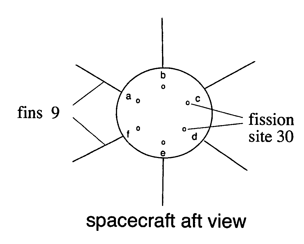
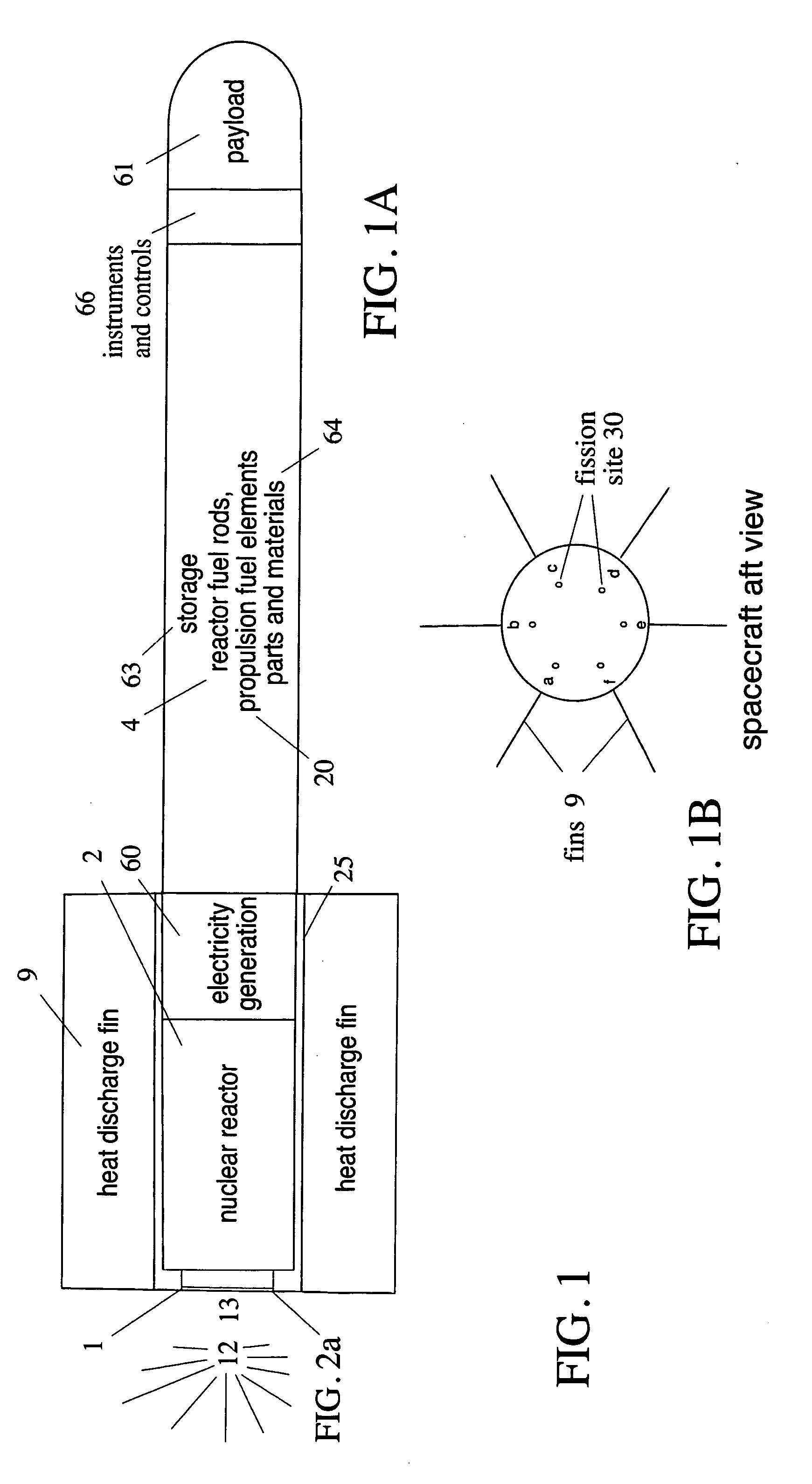
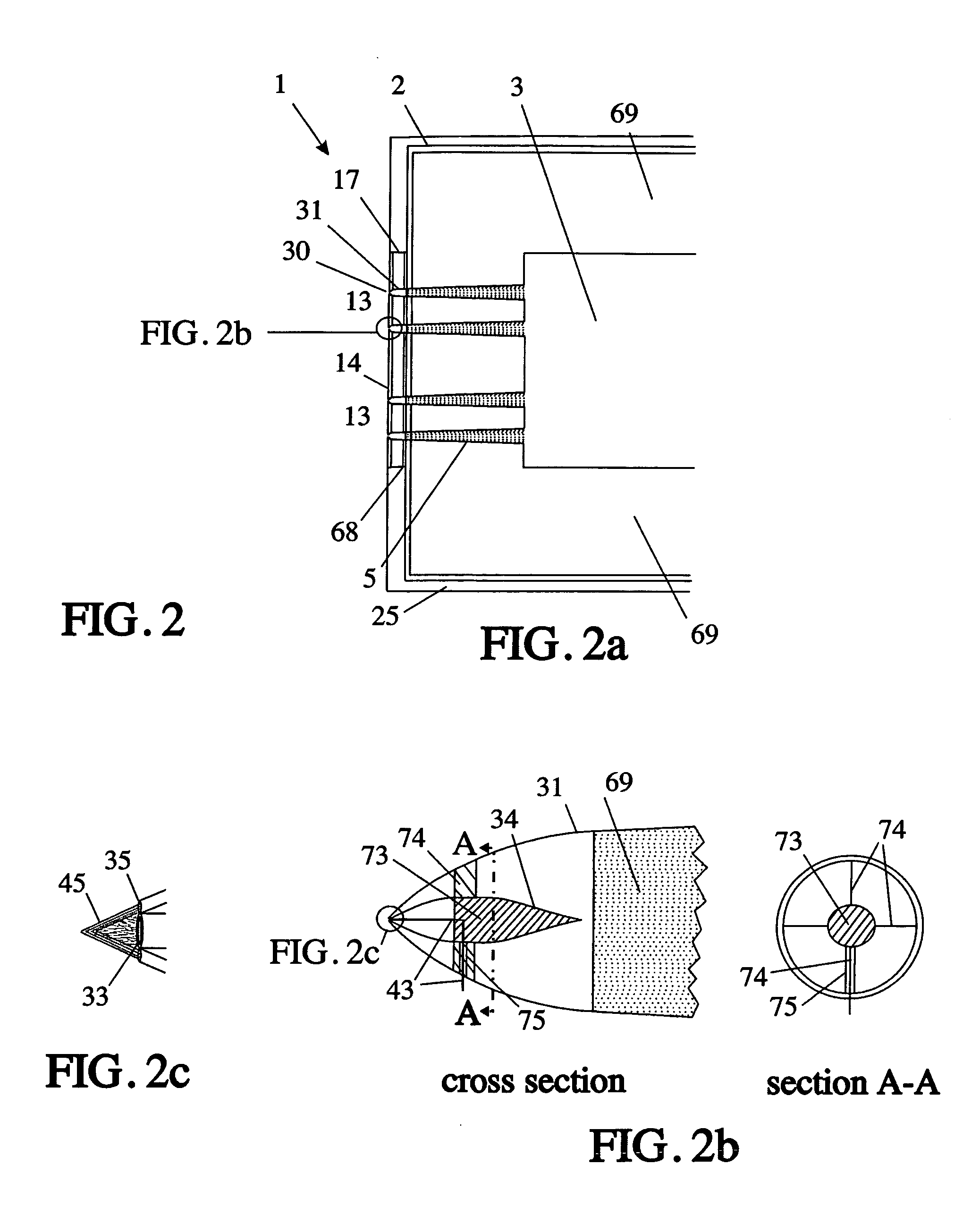
[0024] Referring now to the drawings, wherein like reference numerals designate like or corresponding parts throughout the views, there is shown in FIG. 1, FIG. 2, FIG. 3 and FIG. 4 a nuclear fission fragment kinetic energy rocket engine. Said engine structure comprises an HSHE 17 and a fission zone 13 containing a shield wall 14 and multiple fission sites 30. Said HSHE comprises a heat sink 16, fissionable fuel tubing 43, neutron injectors 3, and a molten metal coolant zone 50 with inlet piping 52 and outlet piping 54.

[0025] The direct usage of fission fragment kinetic energy to produce spacecraft thrust, the foundation of this invention, allows major structural simplifications from those common to nuclear rocket prior art. The FKR engine has no outer shell or convergent-divergent nozzle, therefore its structure is not required to withstand high operating pressures. By freeing the propulsion fission zone 13 from any form of restricting outer structure aft of its shield wall, a por...


PUM


Abstract

A unique space propulsion engine is disclosed, which directly uses the kinetic energies of nuclear fission fragments to generate thrust. At the moment of fission, approximately 85% of the total energy produced is kinetic, contained within fission fragments traveling at 4% the speed of light. The propulsion of rockets and other space devices is conventionally accomplished by hurling mass overboard at high velocities, in accordance with the principles of Newton's third law of motion. An important parameter for quantifying propulsion performance is specific impulse (Isp). Propulsion technologies that support today's rocket missions are primarily based on chemical reactions to produce thrust, and are characterized by Isp values peaking at about 400 seconds. Space concepts using nuclear energy solid-core reactors to heat and exhaust a stored material might operate up to 800 seconds, while more advanced nuclear gas-core reactors and nuclear explosive propulsion have a theoretical limit in the 3000-6000 seconds range. The theoretical Isp of fission fragment kinetic energy propulsion is 1,220,000 seconds, a quantum leap above current technologies and other advanced concepts, up to the level essential for missions to the outer reaches of our solar system and beyond.

Description

FEDERALLY SPONSORED RESEARCH [0001] Not Applicable SEQUENCE LISTING OR PROGRAM [0002] Not Applicable FIELD OF THE INVENTION [0003] This invention relates to a propulsion engine for travel to the outer reaches of our solar system and beyond. More specifically, it relates to a unique structure to perform space propulsion, directly utilizing the kinetic energy of atom fragments produced by nuclear fissions. BACKGROUND OF THE INVENTION [0004] Newtons's third law of motion teaches that rocket propulsion is based on the reaction principle—for every action there is an equal and opposite reaction. The thrust that propels a rocket in the forward direction is the opposite reaction force on its structure due to the action force, which is created by the ejection of high-velocity matter in the aft direction.1 1 Pedersen, page 15; Young and Freedman, page 8-7; Zaehringer, page 54. [0005] Chemical propulsion, by far the most common of all concepts in use today for rockets and other space-related p...

Claims


Application Information

Patent Timeline
Patent Type & Authority Applications(United States)
IPC IPC(8): G21D5/02
CPCG21D5/02Y02E30/00
Inventor SUTHERLAND, DONALD GENE
Owner SUTHERLAND DONALD GENE
Why Eureka
Try Eureka