Engine cooling fan with ring reinforcement

a technology of cooling fan and reinforcement ring, which is applied in the direction of liquid fuel engines, vessel construction, marine propulsion, etc., can solve the problems of ice formation between the reinforcement ring and the protective shroud, damage to the fan, engine damage, etc., and achieve the effect of reducing the build-up of ice therebetween

Inactive Publication Date: 2007-06-07
TOYOTA MOTOR ENGINEERING & MANUFACTURING NORTH AMERICA
View PDF4 Cites 4 Cited by
  • Summary
  • Abstract
  • Description
  • Claims
  • Application Information

AI Technical Summary

Benefits of technology

[0009] According to another aspect of the invention, an automotive vehicle includes a fan shroud and a cooling fan. The fan shroud has an outer wall defining a generally cylindrical space. The cooling fan is pivotally coupled to the vehicle. The fan is disposed within the cylindrical space of the fan shroud. The fan has a central hub, a plurality of blades and an annular reinforcement element. The central hub is pivotally coupled to the vehicle. The plurality of blades has distal ends spaced radially outwardly relative to the central hub. The annular reinforcement element is fixedly secured to the plurality of blades, the reinforcement element being spaced apart from the outer wall of the shroud so as to minimize a build-up of ice therebetween.

Problems solved by technology

The problem with the reinforcement ring in conventional fan designs is that in cold environments, ice can form between the reinforcement ring and the protective shroud.
The ice can impede rotational movement of the fan, which can cause damage to the fan when the engine is started.
The engine can also be damaged as heat energy accumulates in the engine and is not properly exhausted by the radiator.

Method used


Image

  • Engine cooling fan with ring reinforcement
  • Engine cooling fan with ring reinforcement

Examples


Embodiment Construction

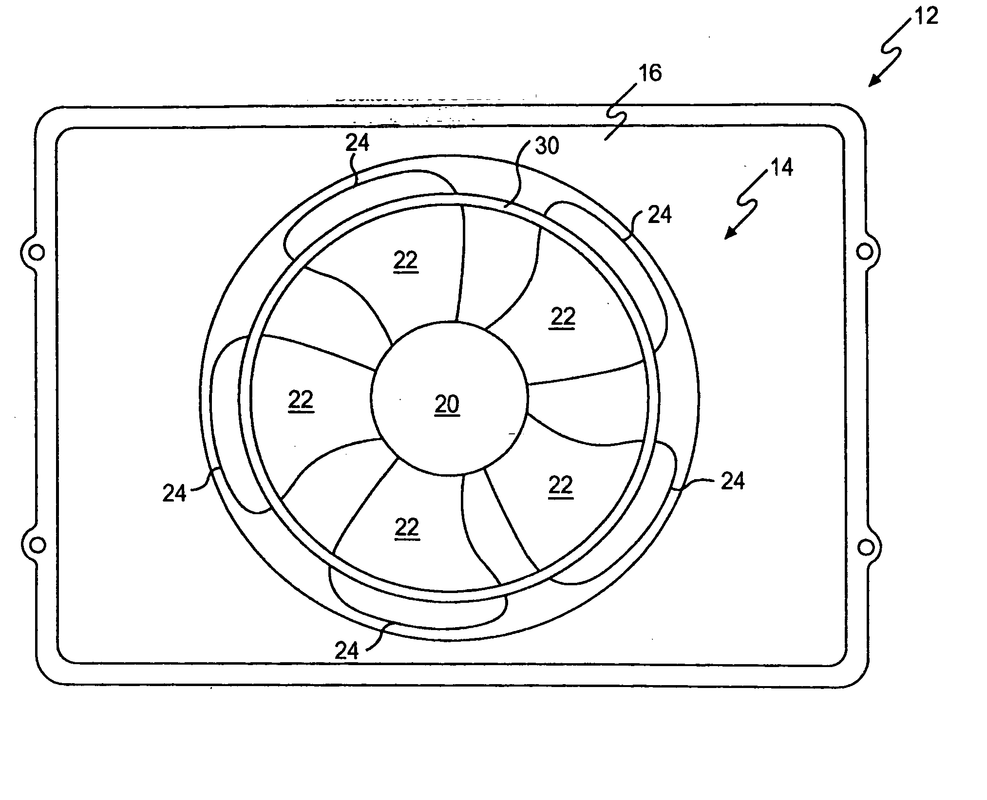
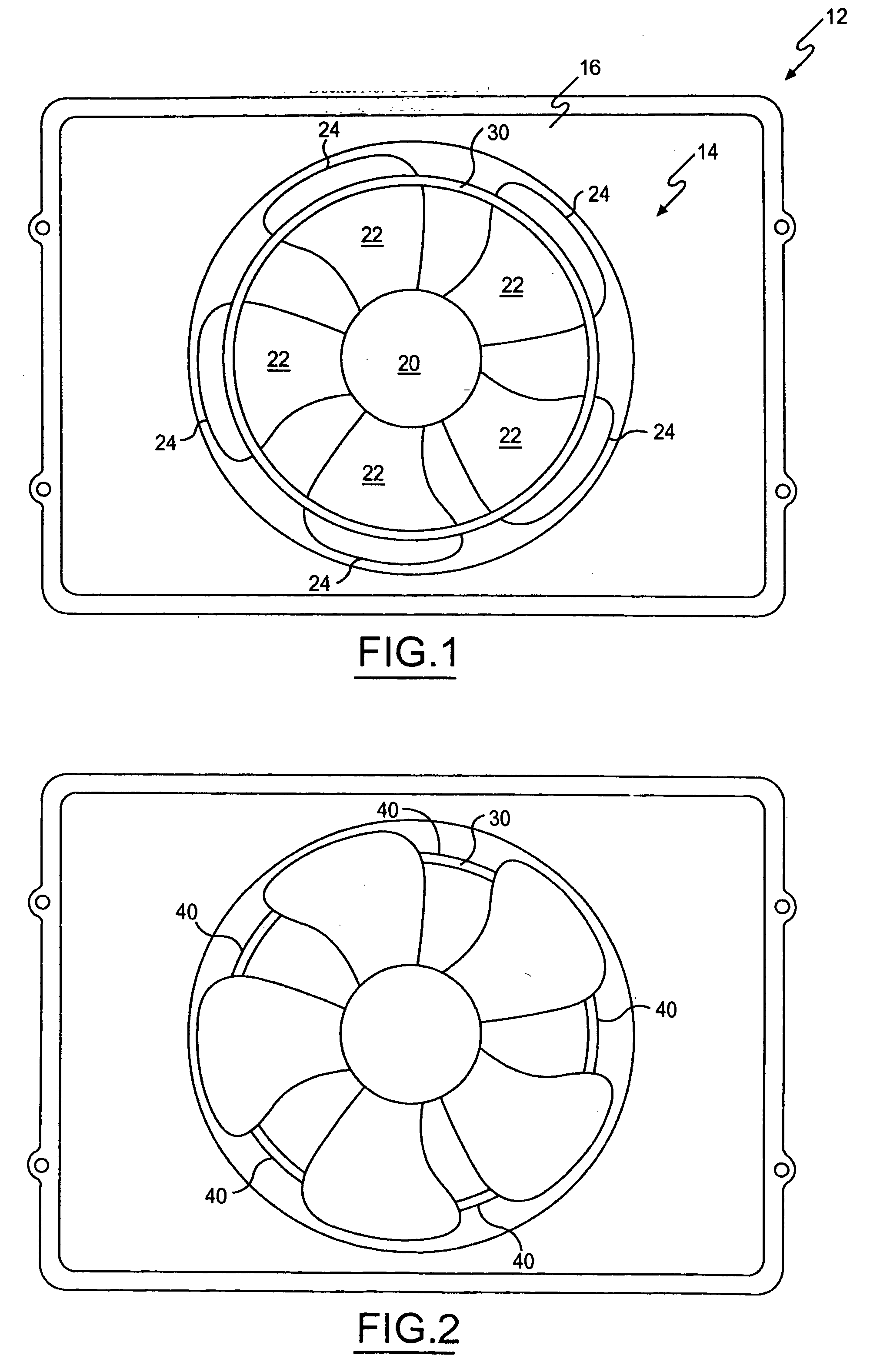
[0014] Referring to FIG. 1, a front end of an automotive vehicle is shown having a radiator 10, a fan shroud 12 and a cooling fan 14. The radiator 10 is of conventional design for cooling liquid passing through a block of an engine by way of heat exchange with air directed toward the radiator 10 while the vehicle is moving and / or with air propelled toward the radiator 10 by rotation of the fan 14. The fan 14 is driven by an engine driven serpentine belt or by an electric motor powered by the vehicle electrical system.

[0015] The fan shroud 12 includes an outer wall 16 defining a generally cylindrical space. The fan 14 is pivotally coupled to the vehicle. The fan 14 is disposed within the cylindrical space.

[0016] The fan 14 includes a central hub 20. The hub 20 is generally cylindrical. The fan 14 includes a plurality of fins or blades 22 shaped for directing air toward the radiator during rotation of the fan 14 in a driven direction. The fan 14 has at least three blades 22. The bla...


PUM


Abstract

A cooling fan for use in an engine of an automotive vehicle includes a central hub, a plurality of blades and an annular reinforcement element. The central hub is pivotally coupled to the vehicle. The plurality of blades has distal ends spaced radially outwardly relative to the central hub. The annular reinforcement element is fixedly secured to the plurality of blades, the reinforcement element is spaced radially inwardly relative to the distal ends of the plurality of blades to prevent a build-up of ice between the fan and a shroud or housing surrounding the fan.

Description

BACKGROUND OF THE INVENTION [0001] 1. Field of the Invention [0002] The invention relates to a cooling fan of an engine for an automotive vehicle. More particularly, the invention relates to a cooling fan having an outer periphery and an annular reinforcement member spaced radially inwardly from the outer periphery. [0003] 2. Description of the Related Art [0004] An automotive vehicle includes an internal combustion engine and a radiator for exhausting heat emitted by the engine. Specifically, liquid is forced through passages and cavities within a block of the engine via an engine-driven impeller. The liquid is heated by the block. Heat is carried away from the block as the liquid passes through the radiator. While the vehicle is moving, air is continuously funneled toward the radiator. Heat is exchanged with the air as it passes around and through the radiator. The heat exchange cools the liquid passing through the radiator. The liquid is returned to the passages and cavities of t...

Claims


Application Information

Patent Timeline
Patent Type & Authority Applications(United States)
IPC IPC(8): B63H1/16
CPCF01P2070/50F04D29/325F04D29/326F04D29/666
Inventor NETT, JONATHAN MICHAEL
Owner TOYOTA MOTOR ENGINEERING & MANUFACTURING NORTH AMERICA
Why Eureka
Try Eureka