Transport device for sterile media

Active Publication Date: 2007-06-07
ERBE ELEKTROMEDIZIN GMBH
View PDF6 Cites 46 Cited by
  • Summary
  • Abstract
  • Description
  • Claims
  • Application Information

AI Technical Summary

Benefits of technology

[0014] It is an object of the invention to provide a transport device for sterile fluids that s

Problems solved by technology

With this known solution, however, the user has available only a specific quantity of the fluid medium, because it is contained in a previously prepared cartridge.
Once this has been opened, any content that remains cannot be put to further use, regardless of how much or how little has been extracted during the actual operation.
When a small device is desired, it can easily happen that the reservoir must be exchanged during the operation, which constitutes a disturbing

Method used


Image

  • Transport device for sterile media
  • Transport device for sterile media
  • Transport device for sterile media

Examples


Embodiment Construction

[0028] In the following description, the same reference numerals are used for identical parts or parts with identical actions.

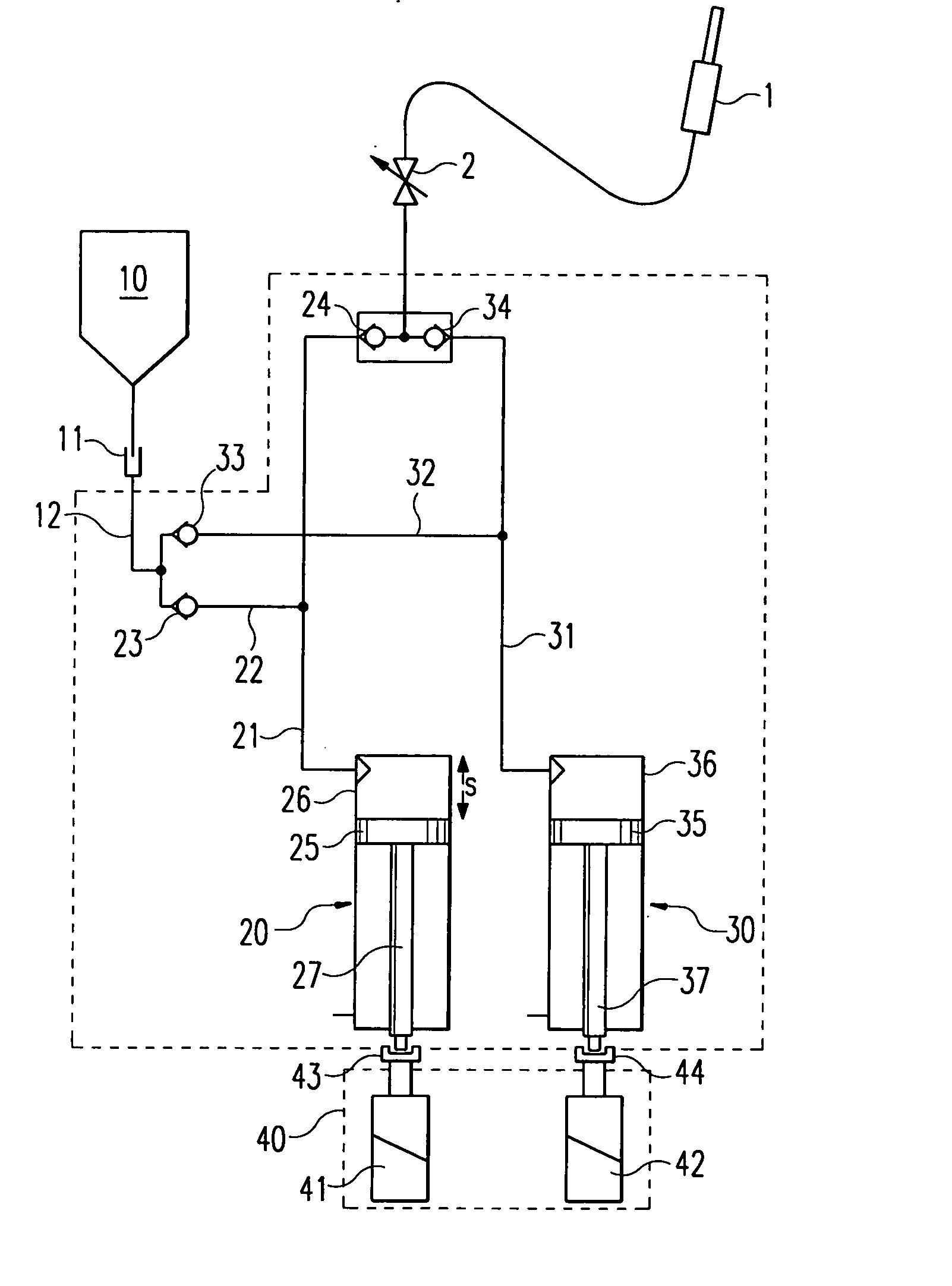
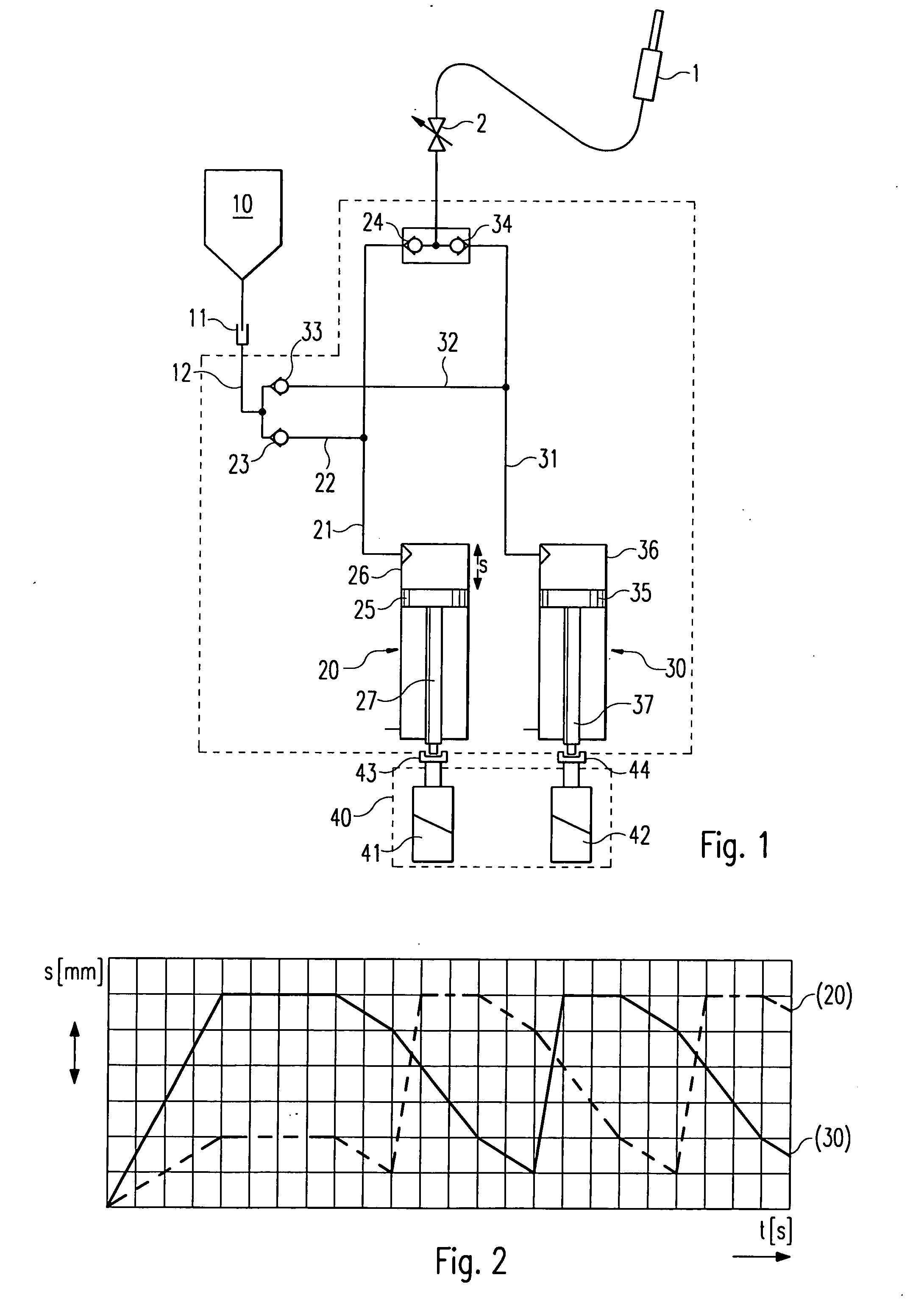
[0029] In the embodiment shown in FIG. 1 there are provided a first pump 20 and a second pump 30, each of which comprises a piston 25; 35, a cylinder 26; 36, a piston rod 27; 37, and a pump conduit 21 or 31 connected to a surgical instrument 1 by way of output valves 24 and 34, respectively, and a clamp valve 2.

[0030] The pump conduits 21 and 31 are connected by way of suction conduits 22 and 32 and suction valves 23 and 33 to a suction conduit 12 that can be connected to a source 10 by way of a releasable coupling 11.

[0031] The piston rods 27 and 37 are releasably connected, by way of a first coupling 43 and second coupling 44, respectively, to a first motor 41 and second motor 42. The parts enclosed by the dashed line in FIG. 1 constitute a disposable unit, which is sterilized and placed in sterile packaging by the manufacturer and is sent in this form t...


PUM


Abstract

For water-jet surgery pump devices are known by means of which a sterile fluid is transported through a reservoir to the surgical instrument by means of piston pumps or similar volumetrically transporting pumps. In accordance with the present invention it is proposed either to construct drive means for the pumps in such a way that their suction cycle is shorter than the output cycle, or to provide a pump with at least three pump chambers and to construct the drive means in such a way that the suction and output cycles of the pump chambers overlap one another.

Description

RELATED U.S. APPLICATIONS [0001] Not applicable. STATEMENT REGARDING FEDERALLY SPONSORED RESEARCH OR DEVELOPMENT [0002] Not applicable. REFERENCE TO MICROFICHE APPENDIX [0003] Not applicable. FIELD OF THE INVENTION [0004] The invention relates to a device for transporting sterile fluids, e.g. Ringer solution, such as are employed for example in water-jet surgery. BACKGROUND OF THE INVENTION [0005] In the area of water-jet surgery—this is an especially important example —in general the following requirements must be met: [0006] The sterility of the fluid must be ensured, because it not only comes into contact with a patient's body but also to some extent remains in the body; [0007] the required flow and / or the pressure needed for such flow must be substantially constant and reproducibly adjustable, to achieve a reproducible effect on the tissue; [0008] the person operating the device must be free to select the duration of an individual activation with constant flow; [0009] containers...

Claims


Application Information

Patent Timeline
IPC IPC(8): A61M1/00A61B17/32
CPCA61B17/3203A61B2019/463A61B2019/464A61B2090/063A61B2090/064
Inventor HAGG, MARTINKUHNER, RALF
Owner ERBE ELEKTROMEDIZIN GMBH
Why Eureka
Try Eureka