Saw blade clamp mechanism

a clamp mechanism and blade technology, applied in metal sawing equipment, metal-working equipment, manufacturing tools, etc., can solve the problems of easy damage to the rotating arms, complicated construction, and easy damage to the clamp mechanism of the blad

Inactive Publication Date: 2007-06-14
POSITEC POWER TOOLS (SUZHOU) CO LTD
View PDF14 Cites 15 Cited by
  • Summary
  • Abstract
  • Description
  • Claims
  • Application Information

AI Technical Summary

Benefits of technology

[0014] Compared with the prior art, the advantage of the present invention is that: the protruding portions are formed on the free end portions of the releasing member and rotatably and movably engaging the sliding rails formed on the outer side surfaces of the body. It is convenient for an operator to mount the releasing member to the body by simply fitting the protruding portions into the sliding rails through open ends of the rails. A hole is defined in a middle portion of the releasing member and rotatably receives the clamping member. The component is of highly rigidity and is thus structural tough against damage such as breaking. Further, because of open ends of the sliding rail, the releasing member is mountable to the sliding rail of the body without elastic deformation / distortion. The releasing member can thus be made of a rigid material, such as metals, and life span is prolonged. Thus, productivity of the clamp mechanism can be enhanced with reduced flaw rate of the product.
is that: the protruding portions are formed on the free end portions of the releasing member and rotatably and movably engaging the sliding rails formed on the outer side surfaces of the body. It is convenient for an operator to mount the releasing member to the body by simply fitting the protruding portions into the sliding rails through open ends of the rails. A hole is defined in a middle portion of the releasing member and rotatably receives the clamping member. The component is of highly rigidity and is thus structural tough against damage such as breaking. Further, because of open ends of the sliding rail, the releasing member is mountable to the sliding rail of the body without elastic deformation / distortion. The releasing member can thus be made of a rigid material, such as metals, and life span is prolonged. Thus, productivity of the clamp mechanism can be enhanced with reduced flaw rate of the product.

Problems solved by technology

The saw blade clamp mechanism includes a variety of components and is thus complicated in construction.
During such a process of mounting the releasing means with elastic deformation of the rotating arms, the rotating arms are prone to damage and breaking caused by inappropriate handling.
This clearly increases manufacture costs and also leads to poor productivity.
The rotating arms are often operated under great forces and are thus easy to invalidate because of distortion and deformation caused by the great forces.

Method used


Image

  • Saw blade clamp mechanism
  • Saw blade clamp mechanism
  • Saw blade clamp mechanism

Examples


Embodiment Construction

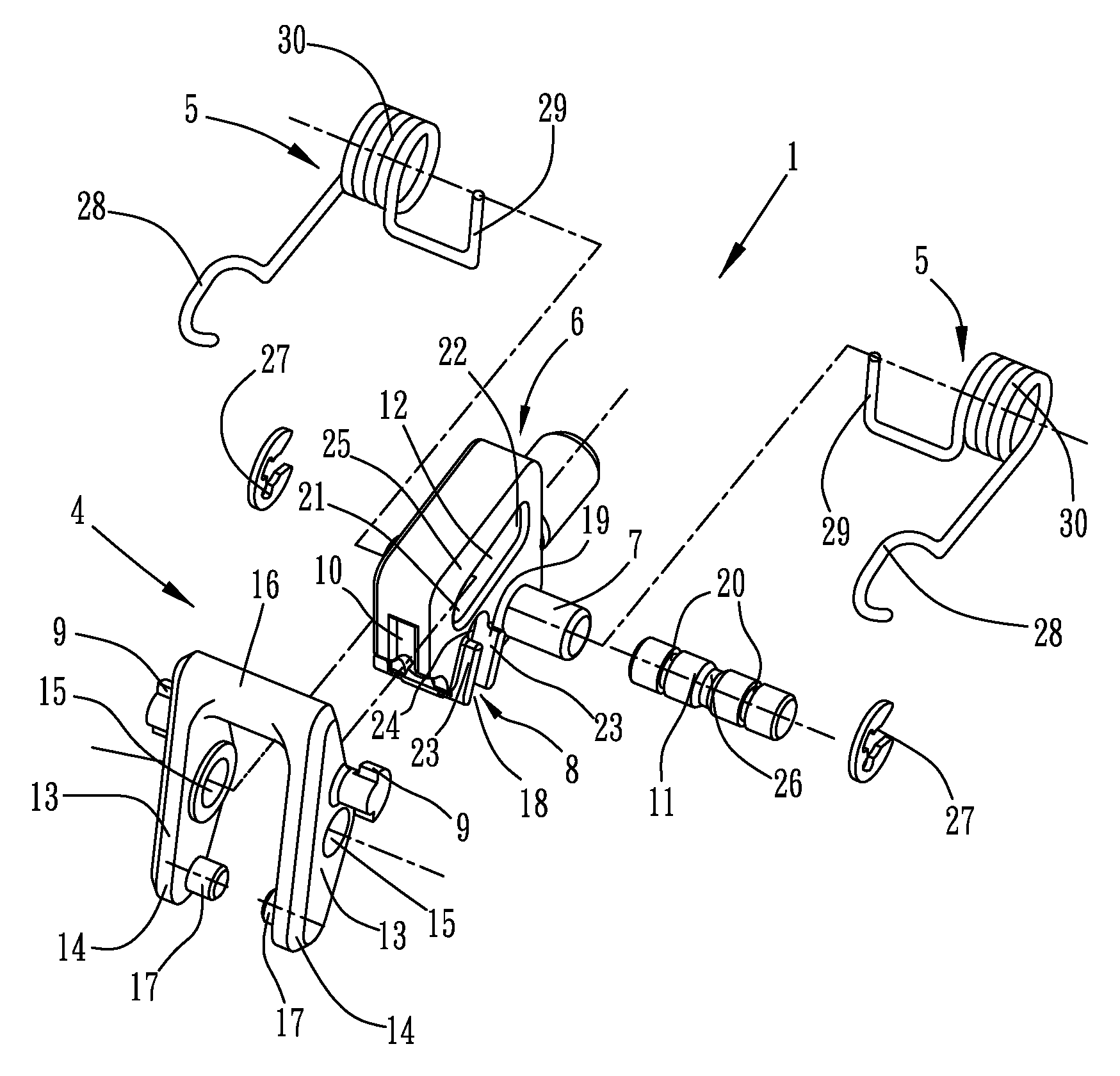
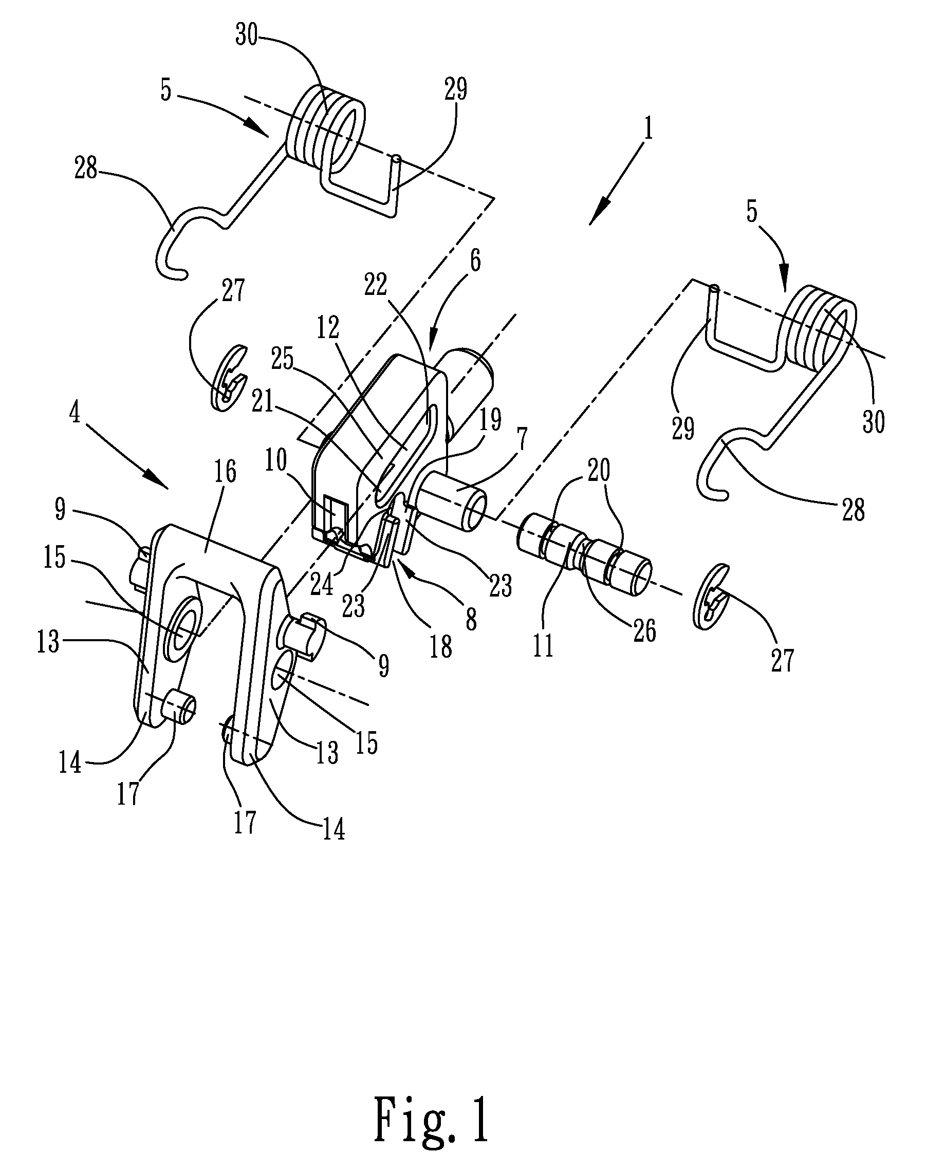
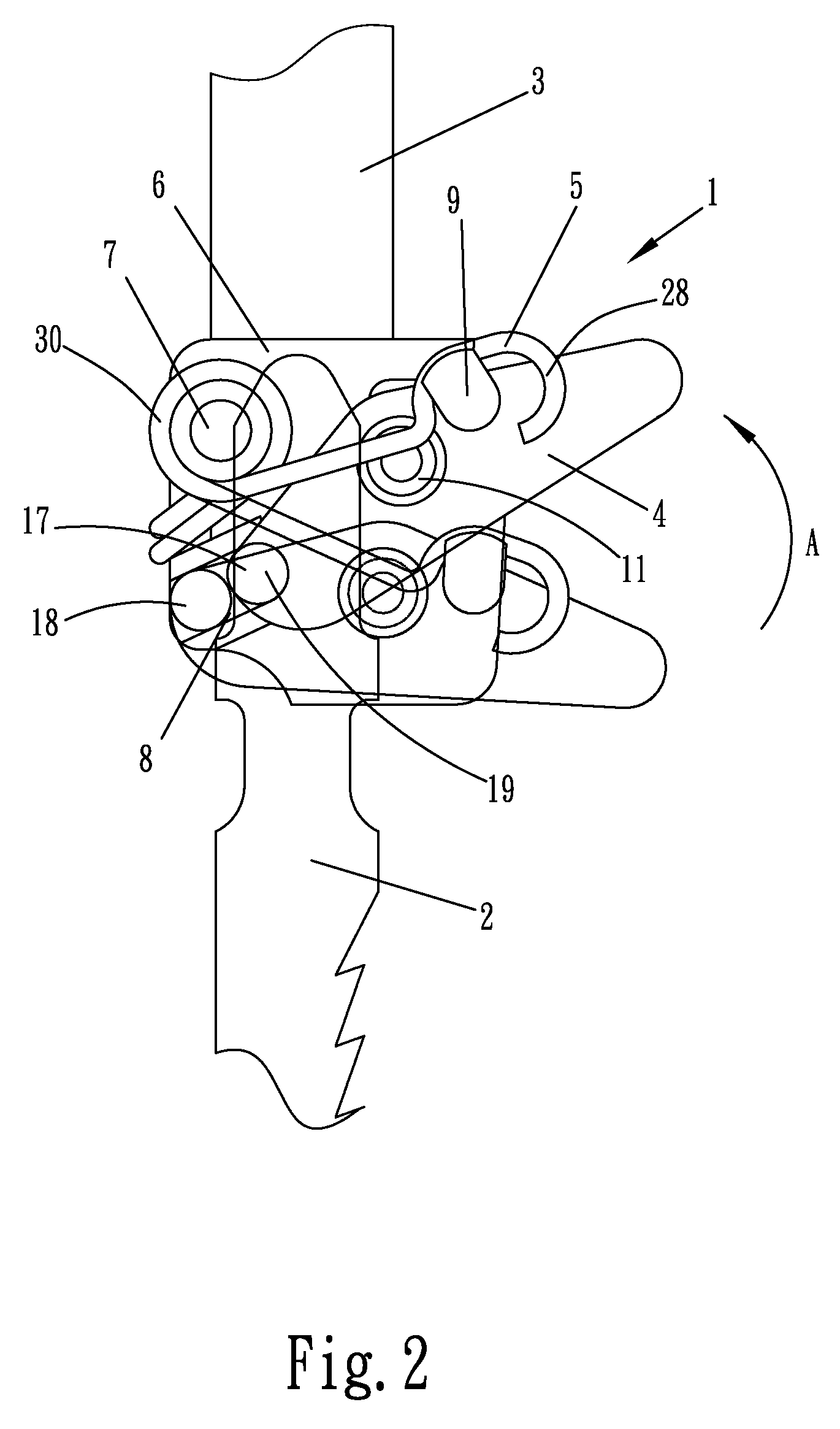
[0021] With reference to FIGS. 1-5, a saw blade clamp mechanism constructed in accordance with the present invention, generally designated with reference numeral 1, is shown. The saw blade clamp mechanism 1 is coupled to a jigsaw (not shown) and function to releasably secure a saw blade. Structural details of the jigsaw and the saw blade are known and constitute no novel part of the present invention so that a description of the jigsaw and the saw blade will be omitted, except for those necessary for describing the clamp mechanism 1 of the present invention. Although the clamp mechanism 1 of the present invention is demonstrated herein to secure a saw blade of a jigsaw, it is apparent that the clamp mechanism 1 is also applicable to other tools, such as a reciprocating saw, or the likes.

[0022] The clamp mechanism 1 comprises a body 6, which is mounted to a reciprocating rod 3 of the jigsaw. The saw blade, which is broadly designated with reference numeral 2, is releasably secured t...


PUM

PropertyMeasurementUnit
biasing forceaaaaaaaaaa
forceaaaaaaaaaa
flexibleaaaaaaaaaa

Abstract

A saw blade clamp mechanism includes a body forming a channel for receiving a saw blade, a clamping member movably mounted to the body for selectively engaging the saw blade, a releasing member in operative coupling with the clamping member, and a biasing element arranged between the body and the releasing member. A sliding rail is formed on at least one outer side surface of the body. The releasing member has a U-shape having an arm forming a protruding portion rotatably and movably received in the sliding rail. The movement of the releasing member along the sliding rail with respect to the body against the biasing element causes the clamping member to secure and / or release the saw blade. The sliding rail has at least one open end to easily receive the protruding portion of the releasing member so as to facilitate mounting / dismounting of the releasing member on the body.

Description

BACKGROUND OF THE INVENTION [0001] 1. Field of the Invention [0002] The present invention relates to a saw blade clamp mechanism, and in particular to a saw blade clamp mechanism that can be assembled in an efficient manner. [0003] 2. The Related Arts [0004] A saw blade clamp mechanism is provided in jigsaw or the likes to secure a saw blade. An example of the saw blade clamp mechanism is illustrated in U.S. Pat. No. 5,987,758, which discloses a saw blade clamp mechanism comprising a body having a blade receiving channel, biasing means connected to a release member and a pair of long linkages, and a clamping member supported by the linkages and the release member. The clamping member is movable in an inclined track formed in the body. The saw blade clamp mechanism includes a variety of components and is thus complicated in construction. [0005] Also, U.S. Pat. No. 6,101,726 discloses a saw blade clamp mechanism, comprising a body having a blade receiving channel, a retaining member t...

Claims


Application Information

Patent Timeline
Patent Type & Authority Applications(United States)
IPC IPC(8): B23D51/10
CPCB23D51/10Y10T83/9457Y10T83/9481
Inventor ZHANG, SHISONGLI, XIANGQING
Owner POSITEC POWER TOOLS (SUZHOU) CO LTD
Why Eureka
Try Eureka