Laser welded plastic intercooler

a technology of intercooler and plastic, applied in the field of intercooler, can solve the problems of increasing cost, time-consuming and expensive, complicating assembly, etc., and achieve the effect of reducing cost and improving manufacturability

Inactive Publication Date: 2007-06-14
SIEMENS VDO AUTOMOTIVE INC
View PDF11 Cites 49 Cited by
  • Summary
  • Abstract
  • Description
  • Claims
  • Application Information

AI Technical Summary

Benefits of technology

[0006] An example intercooler assembly and method of fabricating an intercooler assembly includes features that reduce cost and improves manufacturability.

Problems solved by technology

Each end of each tube is attached and sealed which can be time consuming and expensive.
Each of these considerations can increase cost and complicate assembly.

Method used


Image

  • Laser welded plastic intercooler
  • Laser welded plastic intercooler
  • Laser welded plastic intercooler

Examples


Embodiment Construction

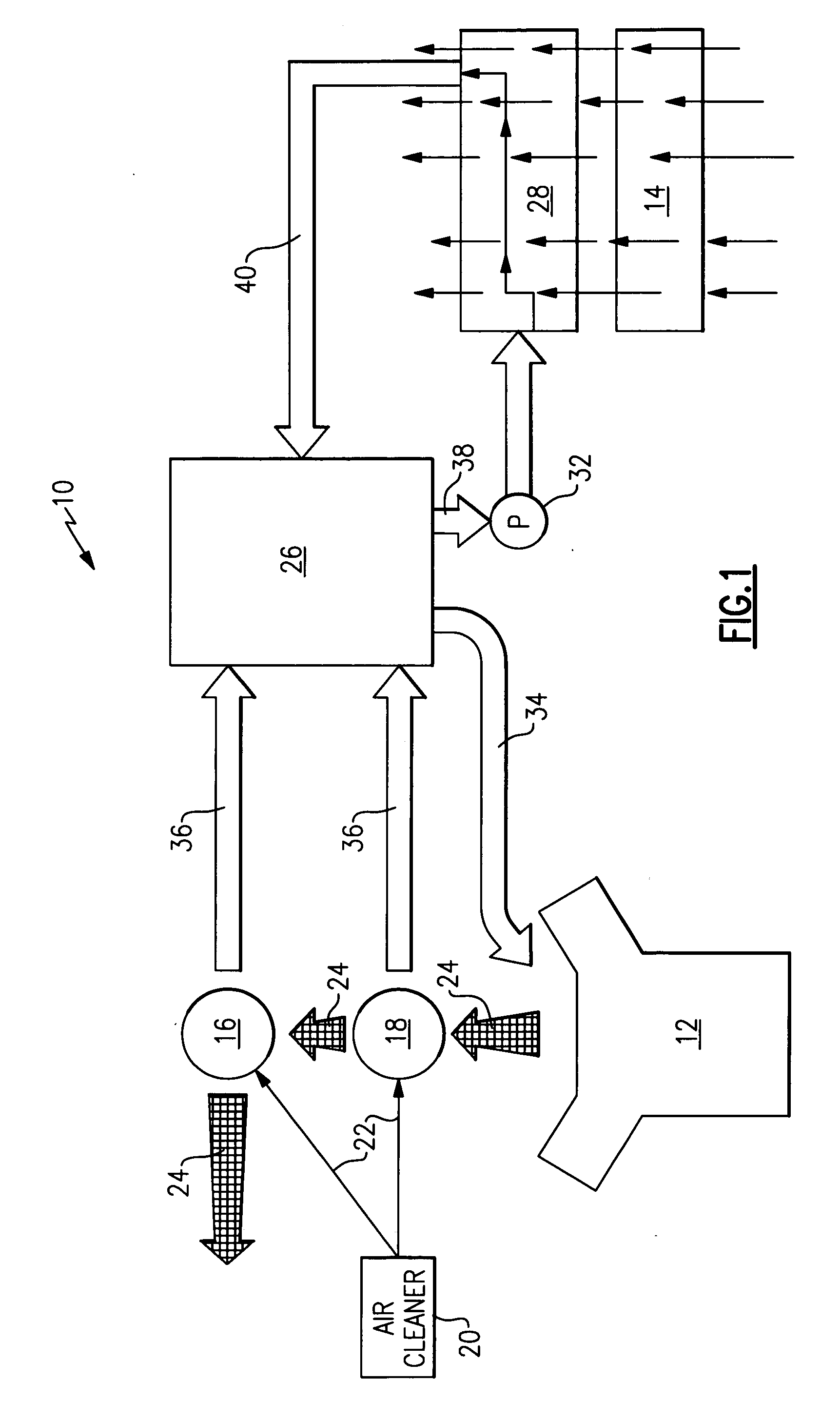
[0029] Referring to FIG. 1 an air induction system 10 for and engine 12 is schematically shown and includes a first turbocharger 16 and a second turbocharger 18 that receives exhaust air 24 from the engine 12. The exhaust air 24 drives the turbochargers 16, 18 to compress or charge air for combustion 22 that is first drawn through an air cleaner 20. The air for combustion 22 is cooled in an intercooler assembly 26.

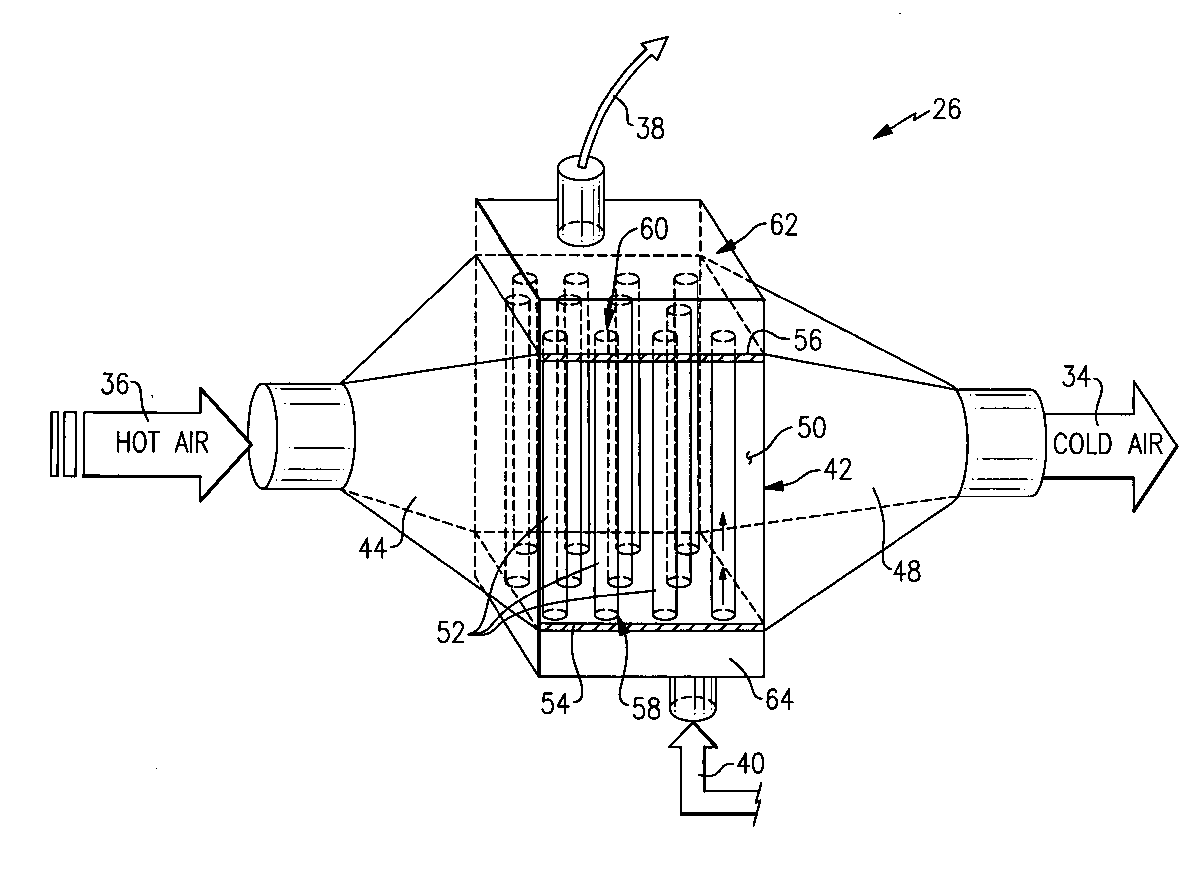
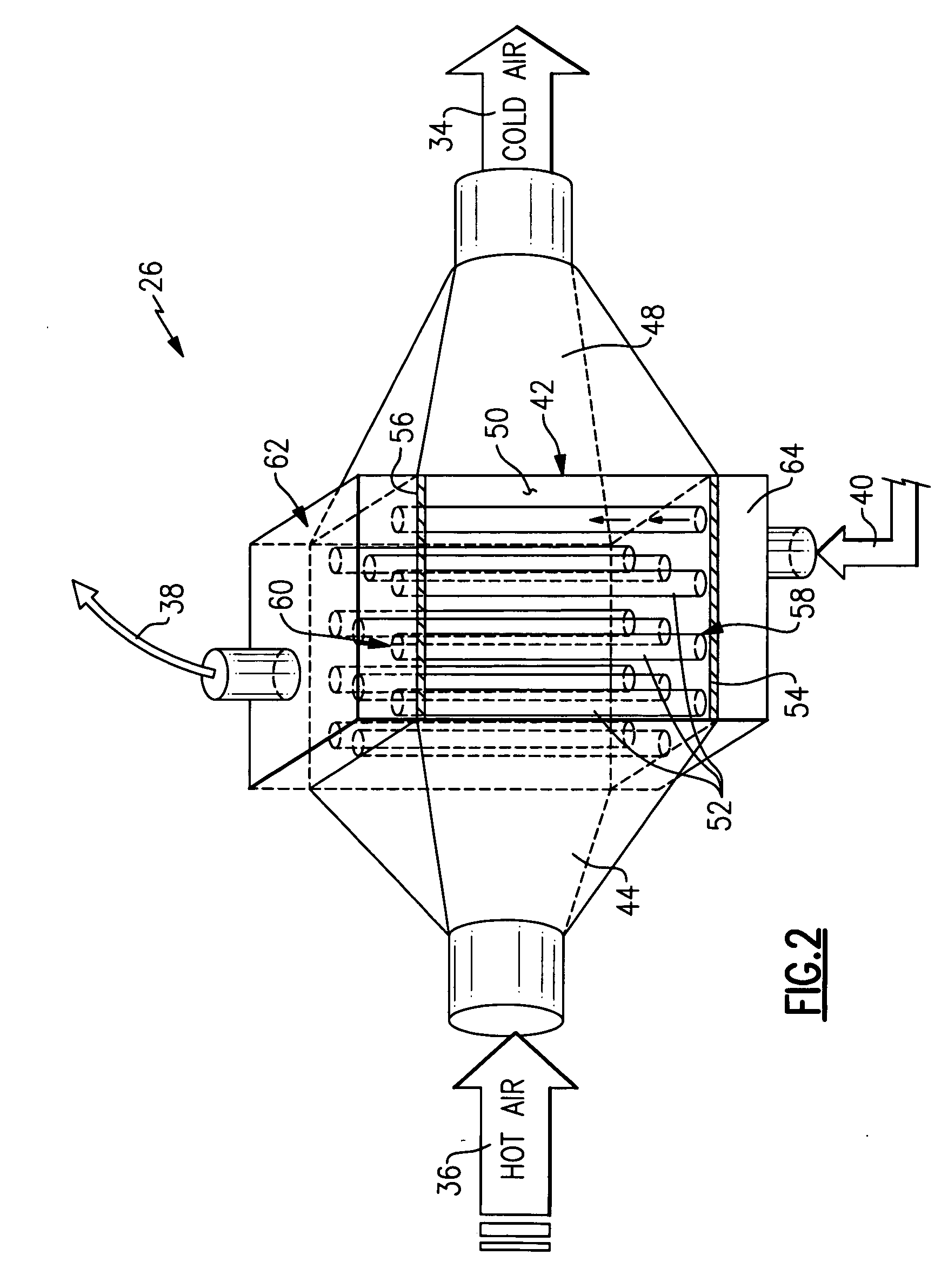
[0030] The intercooler assembly 26 receives hot air 36 which is cooled and exhausted as cooler air 34. The example intercooler assembly 26 circulates a coolant through a plurality of tubes over which and through incoming hot air 36 flows. Heat from the hot air 36 is rejected into the coolant within the intercooler assembly 26. This hot coolant 38 is driven by a pump 32 to a heat exchanger 28 for cooling. Cooled coolant 40 is then re-circulated back to the intercooler assembly 26. The heat exchanger 28 rejects heat from the coolant into an air flow much as an example conve...


PUM

PropertyMeasurementUnit
angleaaaaaaaaaa
radial distanceaaaaaaaaaa
distanceaaaaaaaaaa

Abstract

An intercooler assembly includes a housing that defines an internal space containing a plurality of tubes. A joint between a tube and a tube plate is created by a laser welding process. A form presses the walls of the tube outwardly to form the flange. The downward force of the form not only creates the desired flange, but also exerts a pressure that holds the flange against the tube plate. The form provides for the transmission of laser energy to that the creation of the flange can be performed concurrently with the welding process.

Description

CROSS REFERENCE TO RELATED APPLICATION [0001] This application claims priority to U.S. Provisional Application No. 60 / 749,163 that was filed on Dec. 9, 2005.BACKGROUND OF THE INVENTION [0002] This invention generally relates to an intercooler for cooling an air flow. More particularly, this invention relates to an intercooler constructed utilizing improved fabrication techniques. [0003] An intercooler assembly is commonly utilized to cool an air stream such as charge air from a turbocharger. The intercooler assembly transfers heat between two air streams or between an air stream and a liquid coolant. The basic structure of an intercooler includes a housing that includes a plurality of tubes. A heated air stream flows over and through the plurality of tubes and rejects heat into liquid or a cooler air stream that flows within the tubes. The now heated liquid is then cooled in a heat exchange device and pumped back through the tubes of the intercooler. Heated air that enters the inter...

Claims


Application Information

Patent Timeline
Patent Type & Authority Applications(United States)
IPC IPC(8): F28F9/02
CPCB29C65/1635B29C66/8432B29C65/1664B29C65/1667B29C66/53465B29C66/652B29C66/80B29C66/81267B29C66/81422B29C66/8161B29C66/8242B29L2031/18F02B29/0462F28D7/08F28D7/085F28D7/1615F28D2001/0273F28D2021/0082F28F9/02F28F9/0219F28F9/187F28F21/062F28F2275/062F28F2275/065F28F2275/067Y02T10/146B29C65/1654B29C66/8322B29C66/81463B29C66/843B29C65/00B29C66/1222B29C66/1224B29C66/1226B29C66/73921B29K2995/0027Y02T10/12
Inventor DALY, PAUL D.MCLEAN, IAN R.BAYLIS, BOBBYE KAYE
Owner SIEMENS VDO AUTOMOTIVE INC
Why Eureka
Try Eureka