Drawing-blowing method and device for molding thermoplastic material containers, in particular bottles, with petaloid bottoms

Active Publication Date: 2007-06-14
SIDEL PARTICIPATIONS SAS
View PDF7 Cites 9 Cited by
  • Summary
  • Abstract
  • Description
  • Claims
  • Application Information

AI Technical Summary

Benefits of technology

[0016] An object of the invention is to respond to the primary practical requirement, namely to make it possible for the hot thermoplastic material to be drawn correctly wherever that is necessary, at the same time as avoiding the drawbacks of shouldered drawing rods and the risks of damaging or tearing the hot material associated therewith.
[0017] To these ends, in accordance with a first of its aspects that targets a method as referred to in the preamble, the invention proposes that, during the drawing phase, heat losses are reduced in longitudinal zones of the end part of the preforms, extending over the bottom and over an axial portion of the body of the preforms adjacent to the bottom, which are distributed over the periphery of the ends of the preforms sensibly facing respective cavities of the petaloid mold bottom.
[0018] Accordingly, the thermoplastic material of said longitudinal zones is, thanks to the reduced heat losses, maintained at a higher temperature and is therefore adapted to be drawn in more homogeneous fashion. A result of this is that the feet of the bottoms of the containers feature an increased thickness of material and are mechanically stronger, whereas, the thermoplastic material being better distributed, the bottoms of the containers feature lesser variations of thickness in their diverse portions. Finally, with the same quantity of thermoplastic material assigned to the production of each bottom of complex shape, stronger bottoms are obtained.
[0019] Preferably, according to the invention, for the drawing, a drawing rod is used that includes an end part, the external surface whereof features a plurality of recessed zones equal in number to the number of cavities of the mold bottom and angularly distributed identically to the angular distribution of said cavities, and said drawing rod is locked against rotation in a predetermined angular position such that said recessed zones are situated substantially facing the cavities of the petaloid mold bottom. Thus the hot thermoplastic material of a preform situated in said recessed zones does not come into contact with the drawing rod and suffers lower heat loss; thus held at a higher temperature, it can, during the drawing and blowing steps, be drawn more easily and with a greater amplitude of displacement precisely where that is required, namely in the areas in which the feet are formed. Moreover, the use of these arrangements does not affect in any way the structure of the component parts of the mold and of the molding device other than the drawing rod.

Problems solved by technology

As a result of this, the thermoplastic material, becoming cooler, at least locally, loses a portion of its drawing capacity.
The consequence is that, because of the insufficient mobility of the thermoplastic material during blowing, and regardless of the time at which it begins after the drawing rod has touched the bottom of the preform, too great a quantity of material remains in the central area of the bottom of the container in corresponding relationship to the position of the bottom of the preform.
This drawback is relatively unimportant when manufacturing containers with standard bottoms that feature reliefs that are relatively little differentiated and does not affect the quality of manufacture of such containers.
However, for containers having normal or small capacities (that is to say having capacities not exceeding approximately 2 liters), this drawback is relatively unimportant and until now no compensation has been envisaged for this type of container.
On the other hand, for containers of significantly greater capacity (for example 3 or 3.5 liter containers), the difference in dimensions between the feet and the valleys becomes much greater and such that it is no longer possible to produce petaloid bottoms of correct shape under the conditions presently applying to containers of smaller capacity.
However, this shouldered drawing rod has the drawback of being aggressive with respect to the preforms.
The hot thermoplastic material, which is fragile and easily torn, can easily be pierced by the smaller diameter end of the rod because the thrust force communicated by the rod to the bottom of the preform is applied over a reduced area; what is more, the peripheral edge of the shoulder, if it comes into contact with the thermoplastic material, may mark it or even cause it to tear.

Method used


Image

  • Drawing-blowing method and device for molding thermoplastic material containers, in particular bottles, with petaloid bottoms
  • Drawing-blowing method and device for molding thermoplastic material containers, in particular bottles, with petaloid bottoms
  • Drawing-blowing method and device for molding thermoplastic material containers, in particular bottles, with petaloid bottoms

Examples


Embodiment Construction

[0036]FIG. 5 is now referred to first, in which members and parts identical to those of FIGS. 1 to 4 are designated by the same reference numbers.

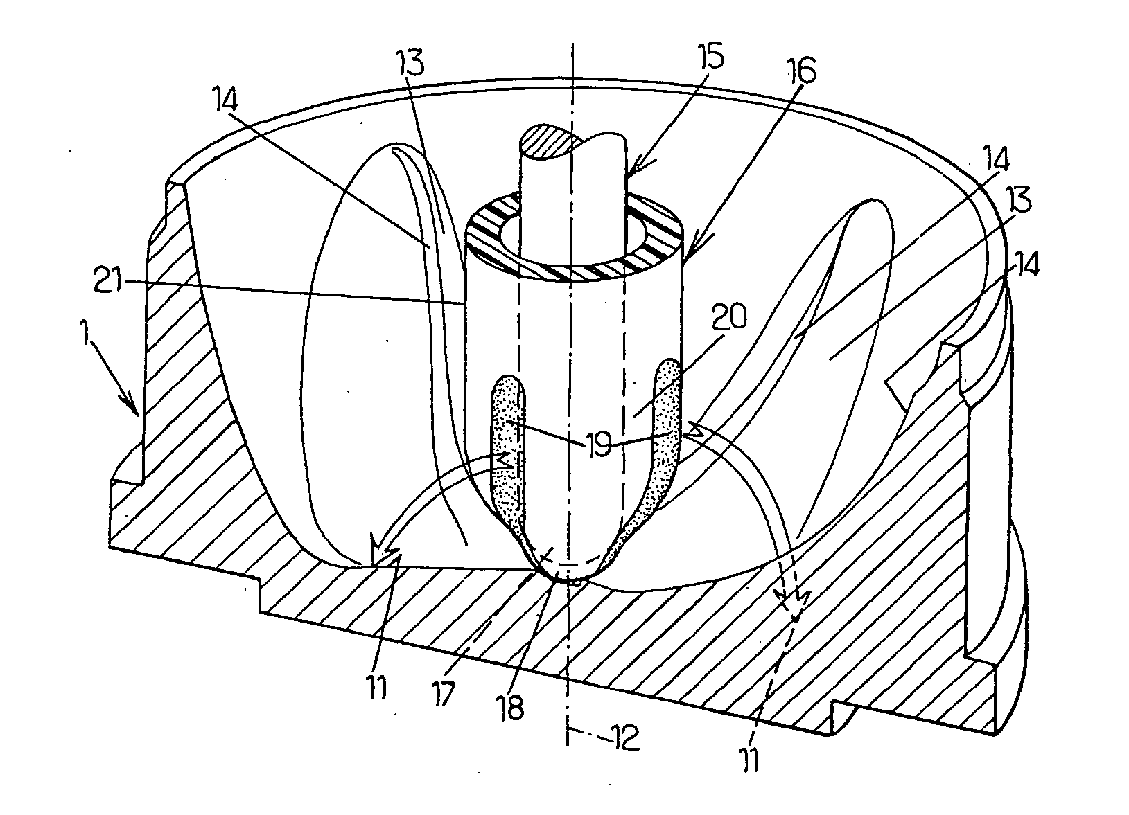
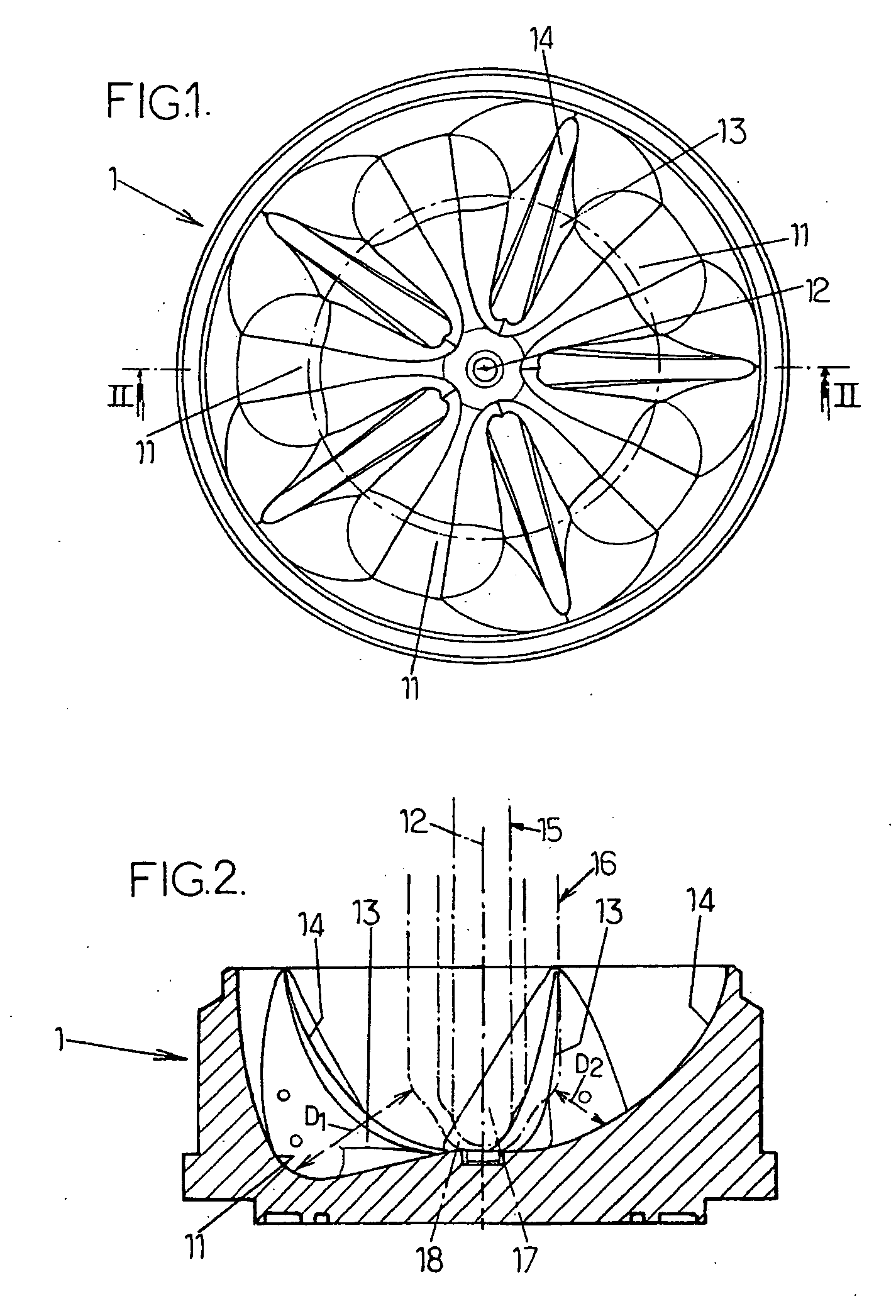
[0037] In accordance with the invention, it is provided that, during the drawing phase, the heat losses are reduced in the longitudinal zones 19 of the end portion 20 of the preform 16, extending over the bottom 18 of the latter and over an axial portion of the body 21 of the preform adjacent to said bottom 18, which are distributed over the periphery of the end of the preform substantially facing the respective cavities 11 of the mold bottom 1.

[0038] Thanks to this arrangement, the thermoplastic material of said longitudinal zones 19 remains at a higher temperature than that it had in the usual solution and it is therefore adapted to be drawn in a more homogeneous and better distributed fashion during blowing. Consequently, the thickness of the bottom is more uniform throughout: the central portion of the bottom is of reduced thickness ...


PUM

PropertyMeasurementUnit
Angleaaaaaaaaaa
Diameteraaaaaaaaaa
Depthaaaaaaaaaa

Abstract

The invention relates to manufacturing thermoplastic material containers (2) with a petaloid bottom (4) by drawing-blowing hot preforms (16) in a blowing mold that has a petaloid mold bottom (1) including radiating ridges (13) alternating with cavities (11) that are adapted to form the valleys (7) and the feet (5), respectively, of the container bottom; during drawing, heat losses are reduced in longitudinal zones (19) of the end part (20) of the preforms, extending over the bottom (18) and over an axial portion of their body (21), distributed over the periphery of the ends of the preforms facing respective cavities (11) of the mold bottom (1).

Description

FIELD OF THE INVENTION [0001] The present invention relates generally to the field of the manufacture of thermoplastic material, such as PET, containers, in particular bottles, and it relates more specifically to improvements made to molding methods and devices for the manufacture of thermoplastic material containers, in particular bottles, with petaloid bottoms by drawing-blowing from hot preforms in a blowing mold that also has a petaloid bottom including a plurality of radiating ridges alternating with cavities that are adapted to form, during molding, the valleys and the feet, respectively, of the petaloid bottom of the containers. BACKGROUND OF THE INVENTION [0002] Referring to FIGS. 1 to 3 of the appended drawings, there is shown therein—respectively in plan view, in diametral section taken along the line II-II in FIG. 1 and in partially cut-away three-quarter perspective view from above—a mold bottom 1 intended to equip a mold (not shown) for the manufacture of thermoplastic ...

Claims


Application Information

Patent Timeline
IPC IPC(8): B29C49/00B29C49/48
CPCB29C49/12B29C49/36B29C49/6436B29C2049/1238B29C2049/4892B65D1/0284B29C49/1215B29C2049/7831B29C2049/7832B29C2049/7862B29C2049/7865
Inventor VIEILLOT, PHILIPPE
Owner SIDEL PARTICIPATIONS SAS
Why Eureka
Try Eureka