Display apparatus and method for driving the same

a display apparatus and display technology, applied in the field of display apparatuses, can solve the problems of difficulty in the supply voltage of a modifying circuit needs to increase correspondingly, and the amount of current supplied to light-emitting devices with low current-luminance efficiency to obtain rgb-balanced illumination brightness, so as to achieve the effect of driving the display apparatus without reducing the display quality, without increasing the amplitude of input image signals,

Inactive Publication Date: 2007-06-14
CANON KK
View PDF17 Cites 29 Cited by
  • Summary
  • Abstract
  • Description
  • Claims
  • Application Information

AI Technical Summary

Benefits of technology

[0010] The present invention provides a display apparatus capable of supplying a desired current to each pixel column without increasing the amplitude of an input image signal and without reducing the display quality, and a method for driving the display apparatus.

Problems solved by technology

In organic EL panels, a large amount of current is supplied to light-emitting devices having a low current-luminance efficiency to obtain an RGB-balanced illumination brightness.
However, if uniform brightness is achieved by correcting the amplitude of the input image signals, the amplitude will be largely corrected to significantly increase the signal voltage of the specific color, and the power supply voltage of a modifying circuit needs to increase correspondingly, which is undesirable.
In view of a low power supply voltage required for the power supply of a controller IC that controls the amplitude of the input image signals, it is difficult to increase the amplitude of the input image signals.
Further, if the voltage-current conversion gain of the current-data generation circuit is increased for a specific color, there is no compatibility between current generation circuits of different colors.

Method used


Image

  • Display apparatus and method for driving the same
  • Display apparatus and method for driving the same
  • Display apparatus and method for driving the same

Examples


first embodiment

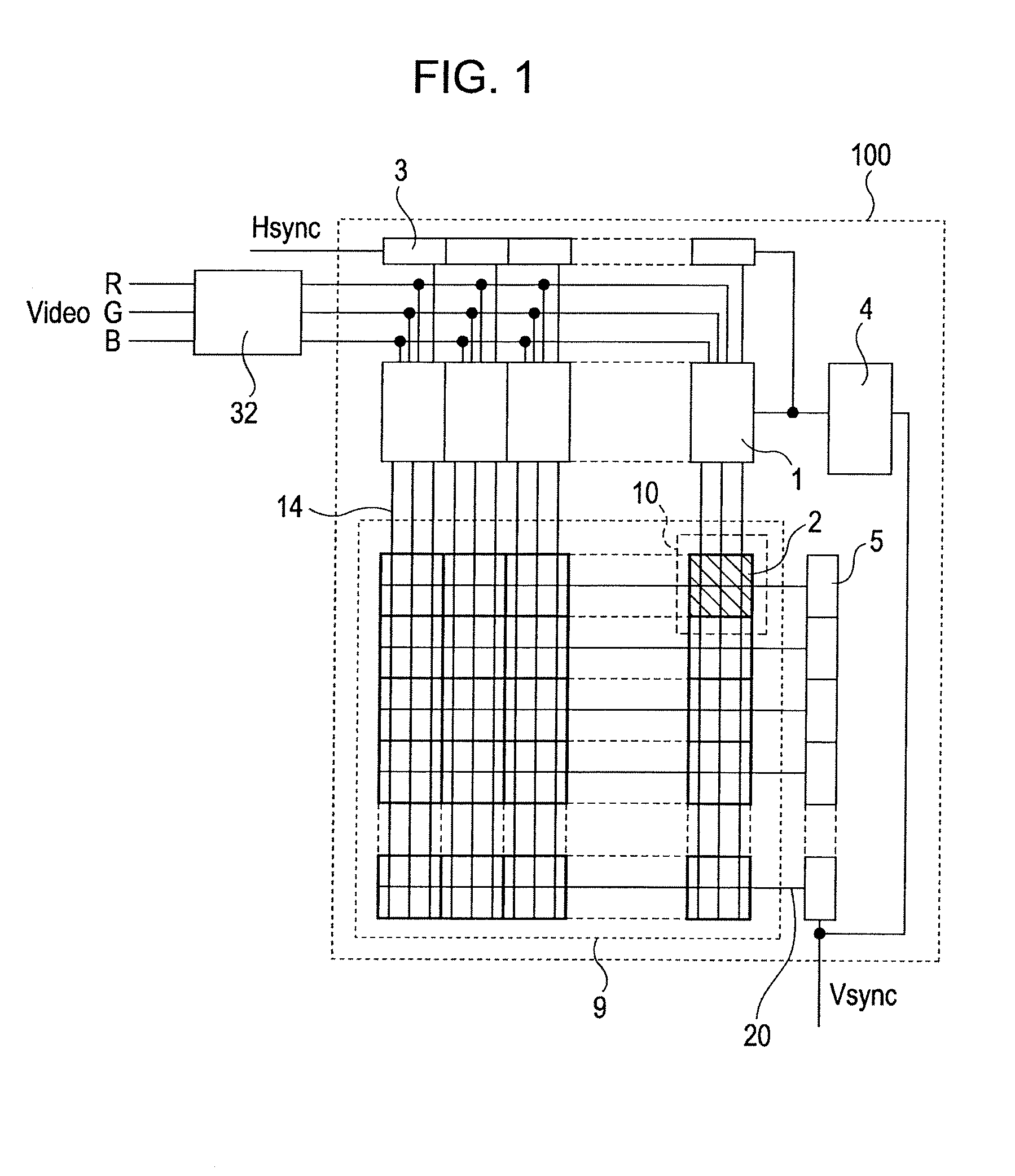
[0035]FIG. 1 shows an overall structure of a display apparatus 100 according to a first embodiment of the present invention.

[0036] The display apparatus 100 includes light-emitting devices and circuits that are formed on a single substrate. A data modifying circuit 32 for correcting the amplitude of an input image signal Video is provided outside the display apparatus 100.

[0037] The display apparatus 100 includes a matrix display area 9 that is formed by arranging EL display devices EL 10 and pixel circuits 2 that drive the EL display devices EL in rows and columns. In FIG. 1, each of the pixel circuits 2 is a circuit that drives the EL display device of any of RGB colors.

[0038] When the EL display devices used in the first embodiment display white with a luminance of 500 cd / m2 by turning on all pixels, the following current densities of those pixels were obtained:

R pixels: 120 A / m2

G pixels: 187 A / M2

B pixels: 273 A / M2  (1)

That is, in order to emit light with the maximum brightne...

second embodiment

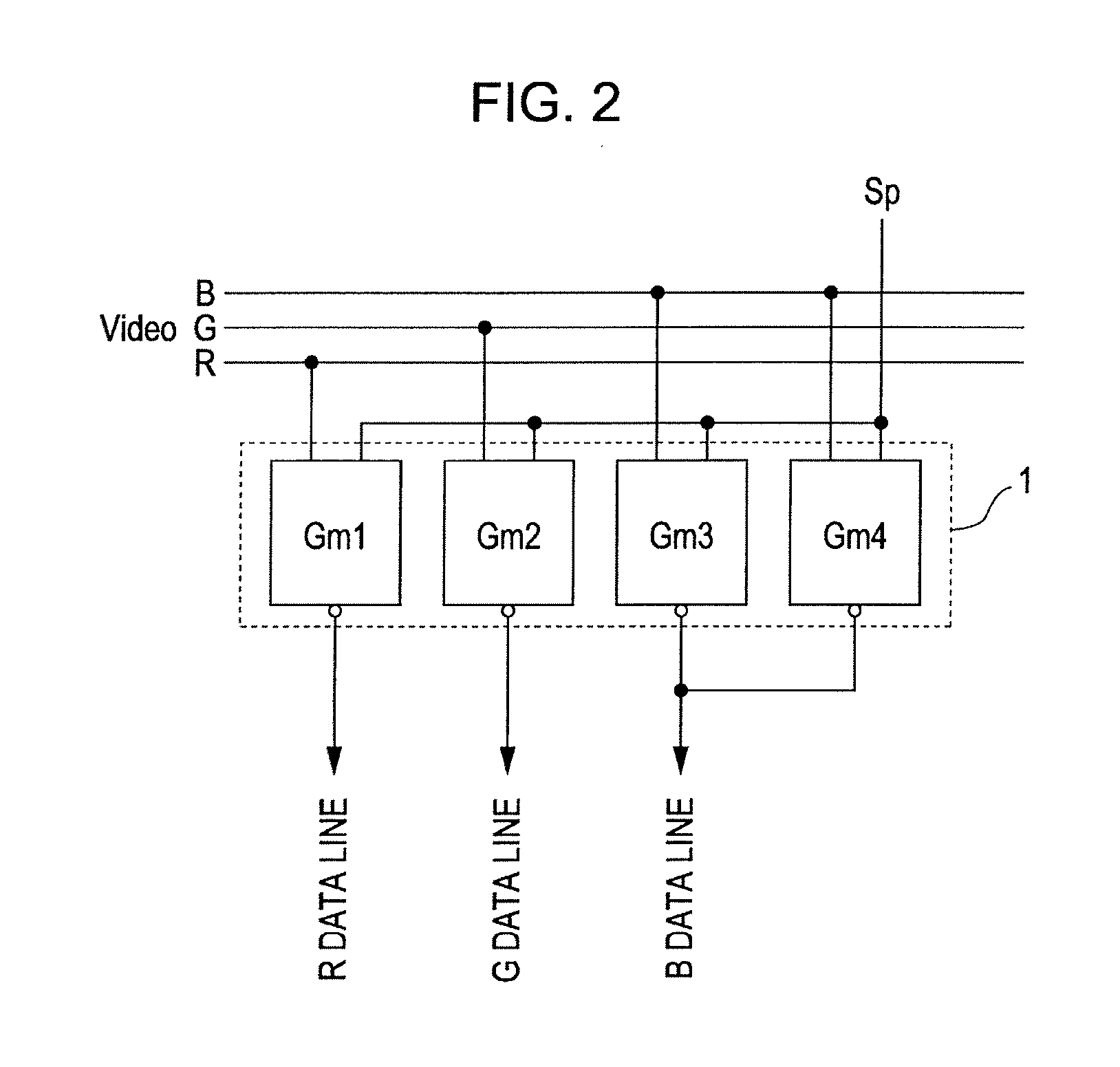
[0062]FIG. 5 shows one set of column control circuit units in a column control circuit according to a second embodiment of the present invention.

[0063] As shown in FIG. 5, a column control circuit 1′ of a display apparatus according to the second embodiment includes a set of four column control circuit units Gm1 to Gm4 and TFT circuits placed upstream and downstream of the column control circuit units Gm1 to Gm4.

[0064] The column control circuit 11 shown in FIG. 5 is different from the column control circuit 1 according to the first embodiment (see FIG. 2) in that an input image signal is not fixedly connected to the column control circuit units Gm1 to Gm4 but can be switched by a first switch 33 and that the output of the column control circuit 1′ is not fixedly connected to the data line but can be switched by a second switch 34.

[0065] First, the operation of the first switch 33 will be described.

[0066] The first switch 33 includes a total of 16 TFTs T11 to T44 that connect th...

third embodiment

[0082] A third embodiment of the present invention provides an electronic apparatus including the display apparatus according to each of the above-described embodiments.

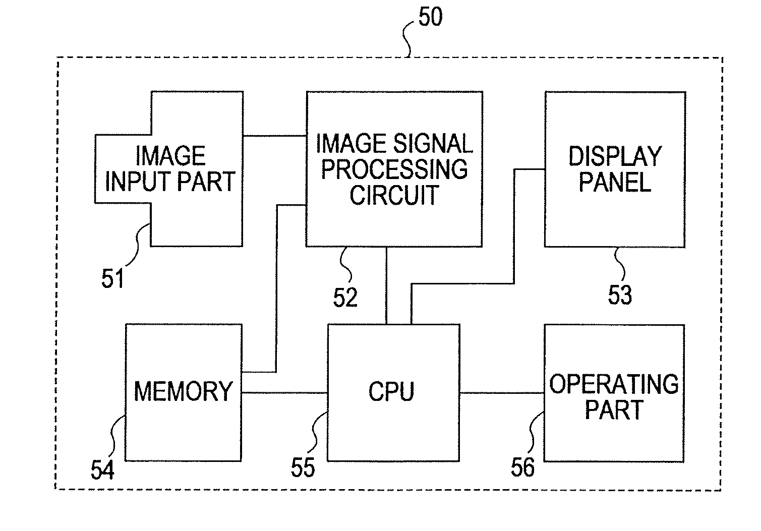
[0083]FIG. 7 is a block diagram showing an example of a digital still camera system 50 according to the third embodiment. In FIG. 7, the digital still camera system 50 includes an image input part 51, an image signal processing circuit 52, a display panel 53, a memory 54, a central processing unit (CPU) 55, and an operating part 56.

[0084] In FIG. 7, an image photographed by the image part 51 or an image recorded on the memory 54 is subjected to signal processing by the image signal processing circuit 52, and can be viewed on the display panel 53. The CPU 55 controls the image input part 51, the memory 54, the image signal processing circuit 52, and the like according to an input from the operating part 56 to perform photographing, recording, playback, and display suitable for the circumstance. The display panel 53 ...


PUM


Abstract

A display apparatus includes a matrix display unit including light-emitting devices of a plurality of colors; a plurality of column control circuits that generate and output current-data signals from input image signals; and data lines that transfer the current-data signal output from the column control circuits to circuits that drive the light-emitting devices in columns. The plurality of column control circuits include a set of column control circuits that output the current-data signals to a set of data lines, the number of which is equal to the number of colors of the light-emitting devices, with the number of column control circuits in the set of column control circuits being larger than the number of colors. The set of column control circuits includes two or more column control circuit units commonly connected to a data line to output the sum of the current-data signals to the connected data line.

Description

BACKGROUND OF THE INVENTION [0001] 1. Field of the Invention [0002] The present invention relates to display apparatuses in which electroluminescent (EL) devices that emit light depending on an input current are arranged in a matrix and to methods for driving the display apparatuses. More specifically, the present invention relates to an active-matrix display apparatus including current-driven light-emitting devices and current-programmed pixel circuits and to a current supplying method for the display apparatus. [0003] 2. Description of the Related Art [0004] Recently, self-illuminating displays including light-emitting devices have attracted attention as next-generation displays. In particular, organic EL devices, which are current-controlled light-emitting devices whose illumination brightness is controlled by a current flowing in the devices, have been extensively applied and developed. [0005] In color organic EL displays, a set of light-emitting devices of three primary colors ...

Claims


Application Information

Patent Timeline
Patent Type & Authority Applications(United States)
IPC IPC(8): G09G5/00
CPCG09G3/325G09G3/3283G09G2300/0842G09G2310/0297G09G2320/0242G09G2320/0666G09G2330/021
Inventor YAMASHITA, TAKANORIKAWASAKI, SOMEI
Owner CANON KK
Why Eureka
Try Eureka