
Three-Dimensional Virtual-Touch Human-Machine Interface System and Method Therefor

a human-machine interface and virtual touch technology, applied in the field of human-machine interfaces, can solve the problems of preventing users from real-time virtual touch and interaction with images, and preventing users from real-time three-dimensional volumetric operation

Active Publication Date: 2007-06-14
MICROSOFT TECH LICENSING LLC
View PDF27 Cites 99 Cited by
  • Summary
  • Abstract
  • Description
  • Claims
  • Application Information

AI Technical Summary

Benefits of technology

The present invention provides a three-dimensional virtual-touch human-machine interface system and method that allows users to interact with images and objects in a realistic and immersive way. The system includes a sensor to detect the position of a user object in a three-dimensional space and a display to show an image in a separate space. When the user object is positioned close to the image, the system can map the user object and the image in the same space, allowing for seamless interaction. The technical effects of this invention include improved user experience, better usability, and more efficient information processing.

Problems solved by technology

However, such 3DHMI systems do not effect a true volumetric interactive environment.
That is, the prior-art 3DHMI systems do not permit users to virtually touch and interact with an image anywhere within a specified volume of space.
Such a two-dimensional interaction plane deprives the user of true three-dimensional volumetric operation.
Such methodologies limit the user to interaction in a field within, upon, or bound by that physical surface.
A disadvantage of the stereo camera concept is that the depth or Z-axis movement of a user object can only be approximated.
This degrades X,Y,Z accuracy, and can result in less robust operation of the system.
Another disadvantage of prior-art 3DHMI systems is that of response time.
The processing of two two-dimensional images into a single three-dimensional image often requires a noticeable amount of time.
This processing lag may lead to errors and false interpretations of user intent.
This lag in response time also inhibits the ability of the system to track movement though the interactive space in substantially real time.

Method used


Image

  • Three-Dimensional Virtual-Touch Human-Machine Interface System and Method Therefor
  • Three-Dimensional Virtual-Touch Human-Machine Interface System and Method Therefor
  • Three-Dimensional Virtual-Touch Human-Machine Interface System and Method Therefor

Examples


Embodiment Construction

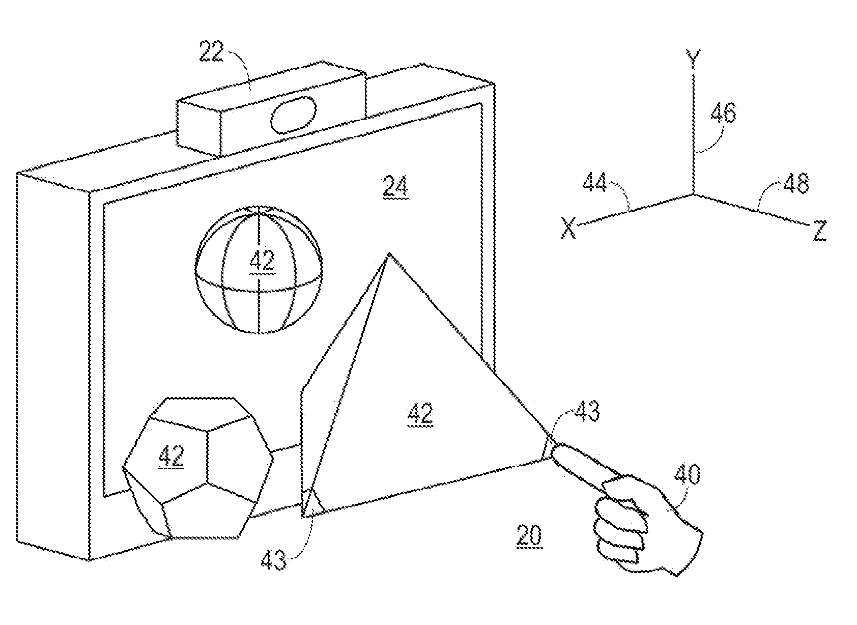
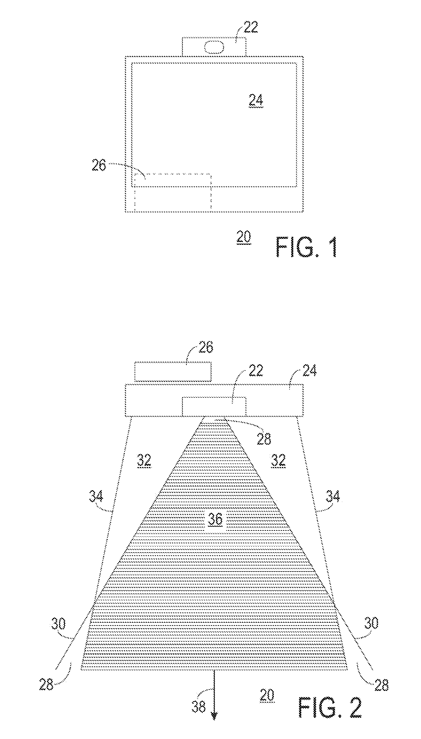
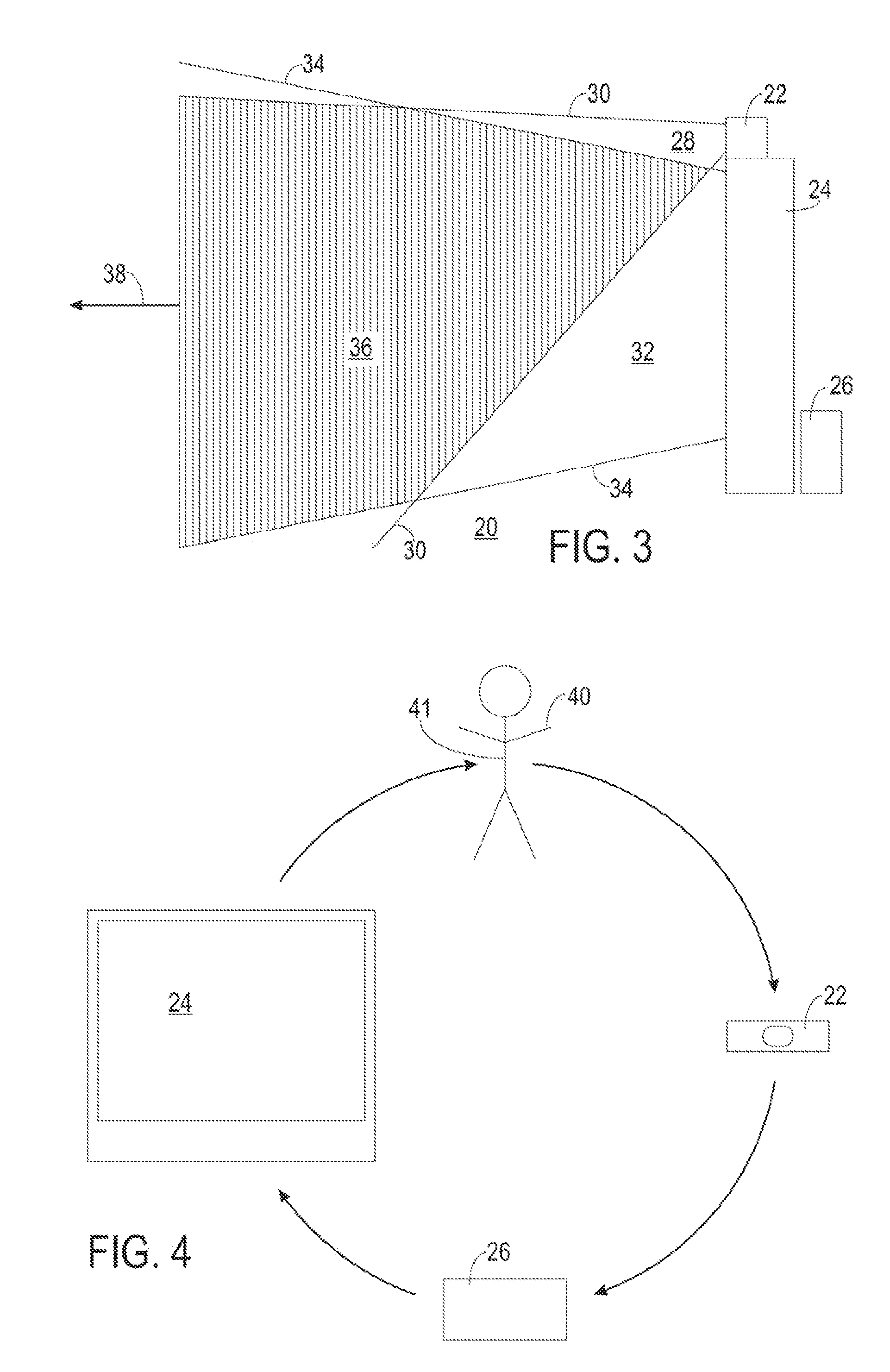
[0025]FIGS. 1, 2, and 3 depict front, top, and side views, respectively, of a three-dimensional virtual-touch human-machine interface (HMI) system 20 in accordance with a preferred embodiment of the present invention. FIGS. 2 and 3 further demonstrate overlapping fields for a three-dimensional object-position sensor 22 and a three-dimensional display 24 of system 20. The following discussion refers to FIGS. 1, 2, and 3.

[0026] System 20 includes three-dimensional object-position sensor 22, three-dimensional display 24, and a computer 26.

[0027] Sensor 22 is a three-dimensional object-position sensor. That is, sensor 22 is configured to detect the position of an object in a three-dimensional sensor space 28. Sensor 22 senses the position of objects within sensor space 28 bounded by sensor field-of-view limits 30. Assuming that sensor field-of-view limits 30 are planes (not a requirement of the present invention), then sensor space 28 is substantially a truncated pyramid having a vert...


PUM


Abstract

A three-dimensional virtual-touch human-machine interface system (20) and a method (100) of operating the system (20) are presented. The system (20) incorporates a three-dimensional time-of-flight sensor (22), a three-dimensional autostereoscopic display (24), and a computer (26) coupled to the sensor (22) and the display (24). The sensor (22) detects a user object (40) within a three-dimensional sensor space (28). The display (24) displays an image (42) within a three-dimensional display space (32). The computer (26) maps a position of the user object (40) within an interactive volumetric field (36) mutually within the sensor space (28) and the display space (32), and determines when the positions of the user object (40) and the image (42) are substantially coincident. Upon detection of coincidence, the computer (26) executes a function programmed for the image (42).

Description

RELATED INVENTIONS [0001] The present invention claims benefit under 35 U.S.C. 119(e) to “3D Virtual-Touch HMI,” U.S. Provisional Patent Application Ser. No. 60 / 749,270, filed 9 Dec. 2005, which is incorporated by reference herein.TECHNICAL FIELD OF THE INVENTION [0002] The present invention relates to the field of human-machine interfaces. More specifically, the present invention relates to the field of human machine interfaces having three-dimensional object sensors and three-dimensional displays. BACKGROUND OF THE INVENTION [0003] Prior-art three-dimensional human-machine interface (3DHMI) systems using three-dimensional displays and three-dimensional object sensors are known. However, such 3DHMI systems do not effect a true volumetric interactive environment. That is, the prior-art 3DHMI systems do not permit users to virtually touch and interact with an image anywhere within a specified volume of space. [0004] Some prior-art 3DHMI systems utilize a planar concept. This concept ...

Claims


Application Information

Patent Timeline
Patent Type & Authority Applications(United States)
IPC IPC(8): G09G5/00
CPCG06F3/011G06F3/0304G06F3/04845G06F3/04815G06F3/04842
Inventor GLOMSKI, WILLIAM E.EL DOKOR, TAREKKING, JOSHUA T.HOLMES, JAMES E.NGOMBA, MARIA N.
Owner MICROSOFT TECH LICENSING LLC
Learn More