Ultra wide angle imaging optical system, ultra wide angle imaging lens device, and image sensing apparatus

Inactive Publication Date: 2007-06-14
KONICA MINOLTA OPTO +3
View PDF4 Cites 33 Cited by
  • Summary
  • Abstract
  • Description
  • Claims
  • Application Information

AI Technical Summary

Benefits of technology

[0018] The above arrangements enable to provide an ultra wide angle imaging optical system, with an ultra wide viewing angle in the first direction e.g. the horizontal direction, a less viewing angle in the second direction e.g. the vertical direction, a relatively less image distortion, and a les

Problems solved by technology

This is because generally a wide area observation is not required in a vertical direction i.e. a height direction of the automobile, and because the car-mounted camera with a wide viewing angle in the vertical direction may capture an image of a high luminance object such as the sun or a street lamp, which may degrade the quality of the monitored image.
As a result, an image distortion resulting from lens distortion may be increased, i

Method used


Image

  • Ultra wide angle imaging optical system, ultra wide angle imaging lens device, and image sensing apparatus
  • Ultra wide angle imaging optical system, ultra wide angle imaging lens device, and image sensing apparatus
  • Ultra wide angle imaging optical system, ultra wide angle imaging lens device, and image sensing apparatus

Examples


Example

EXAMPLE 1

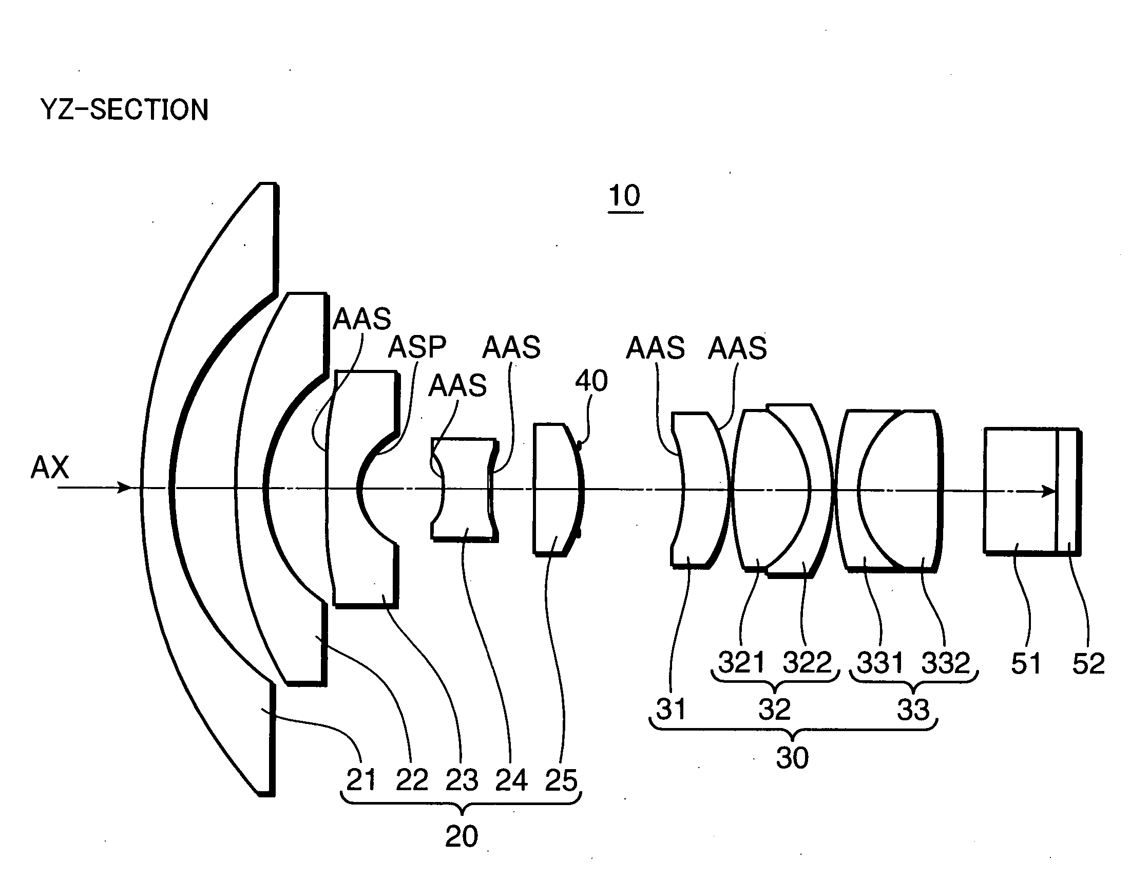
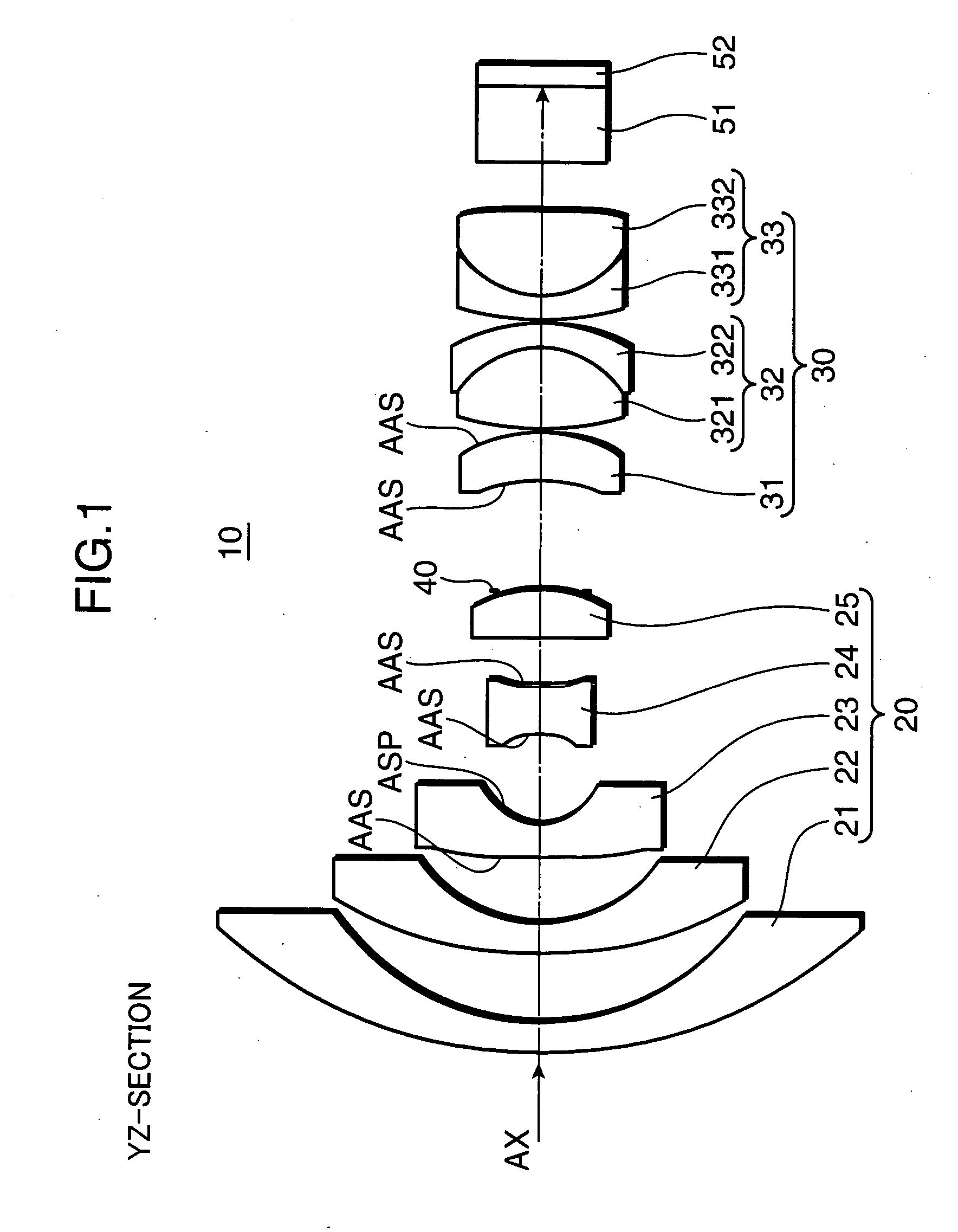
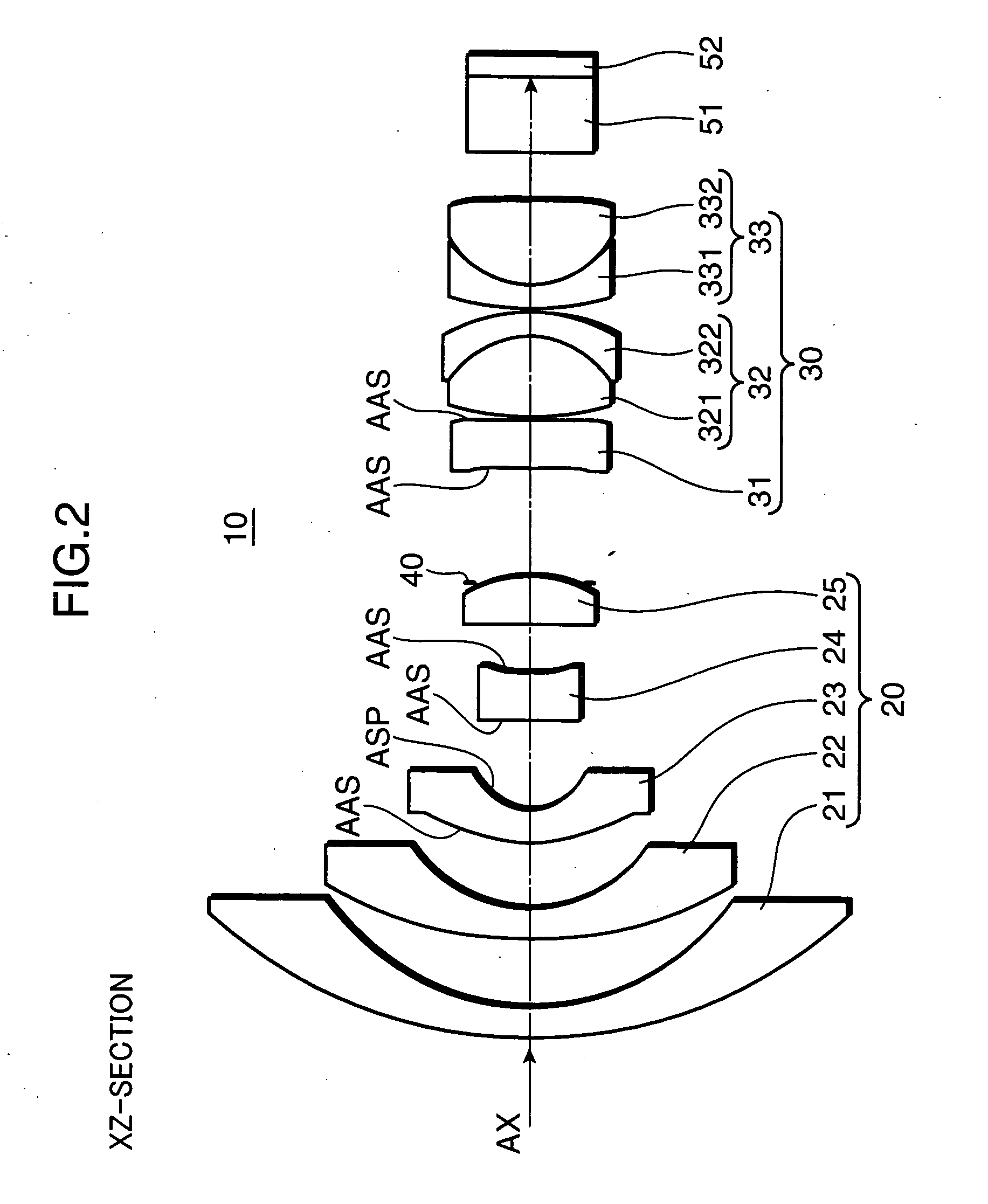
[0070]FIGS. 5 and 6 are cross-sectional views i.e. optical path diagrams longitudinally taken along the optical axis (AX), showing a lens arrangement in an ultra wide angle imaging optical system 10A of Example 1. FIG. 5 shows a horizontal section i.e. the yz-section, and FIG. 6 shows a vertical section i.e. the xz-section. The ultra wide angle imaging optical system 10A includes, from the object side in order, a first lens group (Gr1), an aperture stop (ST), a second lens group (Gr2), a cover glass (CG), and an image sensor (SR).

[0071] The first lens group (Gr1) is constituted of five lens elements in total, i.e., a negative meniscus lens element convex to the object side, as a first lens element (L1); a negative meniscus lens element convex to the object side, as a second lens element (L2); a negative lens element having an anamorphic aspherical surface on the object side, and an aspherical surface on the imaging side, as a third lens element (L3); a negative lens eleme...

Example

EXAMPLE 2

[0095]FIGS. 7 and 8 are cross-sectional views i.e. optical path diagrams longitudinally taken along the optical axis (AX), showing a lens arrangement in an ultra wide angle imaging optical system 10B of Example 2. FIG. 7 shows a horizontal section i.e. the yz-section, and FIG. 8 shows a vertical section i.e. the xz-section. The ultra wide angle imaging optical system 10B includes, from the object side in order, a first lens group (Gr1), an aperture stop (ST), a second lens group (Gr2), a cover glass (CG), and an image sensor (SR).

[0096] The first lens group (Gr1) is constituted of five lens elements in total, i.e., a negative meniscus lens element convex to the object side, as a first lens element (L1); a negative meniscus lens element convex to the object side, as a second lens element (L2); a negative lens element having an anamorphic aspherical surface on the object side, and an aspherical surface on the imaging side, as a third lens element (L3); a negative lens eleme...

Example

EXAMPLE 3

[0110]FIGS. 9 and 10 are cross-sectional views i.e. optical path diagrams longitudinally taken along the optical axis (AX), showing a lens arrangement in an ultra wide angle imaging optical system 10C of Example 3. FIG. 9 shows a horizontal section i.e. the yz-section, and FIG. 10 shows a vertical section i.e. the xz-section. The ultra wide angle imaging optical system 10C includes, from the object side in order, a first lens group (Gr1), an aperture stop (ST), a second lens group (Gr2), a cover glass (CG), and an image sensor (SR).

[0111] The first lens group (Gr1) is constituted of five lens elements in total, i.e., a negative meniscus lens element convex to the object side, as a first lens element (L1); a negative meniscus lens element convex to the object side, as a second lens element (L2); a negative lens element having an anamorphic aspherical surface on the object side, and an aspherical surface on the imaging side, as a third lens element (L3); a negative lens ele...


PUM


Abstract

An ultra wide angle imaging optical system includes, in order from an object side, a first lens group, an aperture stop, and a second lens group. The first lens group includes, in order from the position closest to the object side, a negative meniscus lens element convex to the object side, a negative lens element, and a negative lens element. The second lens group includes a plurality of positive lens elements. The first lens group and the second lens group each includes at least one anamorphic surface having different optical powers with respect to a first section extending in a first direction on a flat plane substantially orthogonal to an optical axis, and with respect to a second section extending in a second direction substantially orthogonal to the first direction. The first lens group includes the lens element satisfying the following conditional formula (1):
−0.6<(Ph−Pv)*(fh+fv)<−0.1  (1)
where Ph: an optical power in the first direction where a viewing angle is large; Pv: an optical power in the second direction where the viewing angle is small; fh: a focal length in the first direction with respect to the entirety of the optical system; and fv: a focal length in the second direction with respect to the entirety of the optical system.

Description

[0001] This application is based on Japanese Patent Application No. 2005-355804 filed on Dec. 9, 2005, the contents of which are hereby incorporated by reference. BACKGROUND OF THE INVENTION [0002] 1. Field of the Invention [0003] The present invention relates to an ultra wide angle imaging optical system having an ultra wide angle of e.g. more than 180 degrees as an entire viewing angle in one direction, an ultra wide angle imaging lens device provided with the ultra wide angle imaging optical system, and an image sensing apparatus mounted with the ultra wide angle imaging lens device, such as a car-mounted camera or a security camera. [0004] 2. Description of the Related Art [0005] Generally, it is preferable to use an imaging optical system having a wide viewing angle i.e. a wide angle lens in a car-mounted camera to be mounted as a back monitor in an automobile, or in a security camera for monitoring a predetermined monitoring area, or in a like device so as to acquire video inf...

Claims


Application Information

Patent Timeline
IPC IPC(8): G02B13/04G02B13/08G02B13/18H04N5/225
CPCG02B13/06
Inventor OHZAWA, SOHINOUE, MASAYUKIIMOTO, MASAYOSHI
Owner KONICA MINOLTA OPTO
Why Eureka
Try Eureka