Wireless headset and control method thereof

a wireless headset and control method technology, applied in the field of wireless headsets, can solve the problems of inconvenient use of the frame, increased overall size of the wireless headset, and difficulty in attaching the wireless headset in the correct position, so as to reduce manufacturing costs, enhance operational stability, and avoid the effect of frame damag

Inactive Publication Date: 2007-06-14
SIMPLEBE +1
View PDF7 Cites 68 Cited by
  • Summary
  • Abstract
  • Description
  • Claims
  • Application Information

AI Technical Summary

Benefits of technology

[0037] According to the present invention as proposed above, the wireless headset can be enhanced in operational stability, can reduce manufacturing costs, can be easily carried, and can

Problems solved by technology

However, this frame is inconvenient to use since a user must attach the headset through a complicated operation.
For example, the user must hook the frame around his or her ear and/or deform the frame, and it is not easy at all to attach the wireless headset in the correct position.
Furthermore, the frame increases the overall size of the wireless headset, and due to its hook-like configuration, is frequently snagged on other objects, such as a pocket.
However, this approach has a drawback in that the wireless headset has limited space inside for co

Method used


Image

  • Wireless headset and control method thereof
  • Wireless headset and control method thereof
  • Wireless headset and control method thereof

Examples


embodiment 1

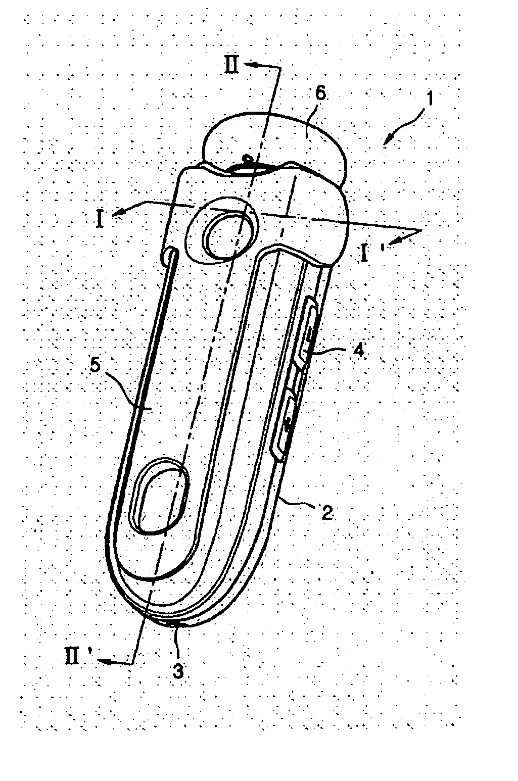
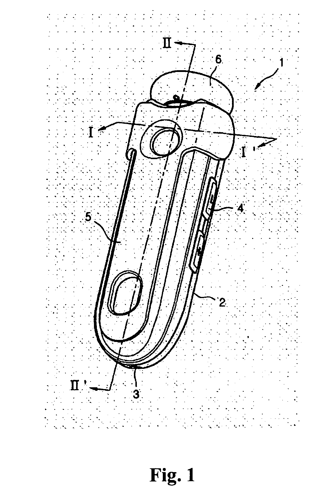
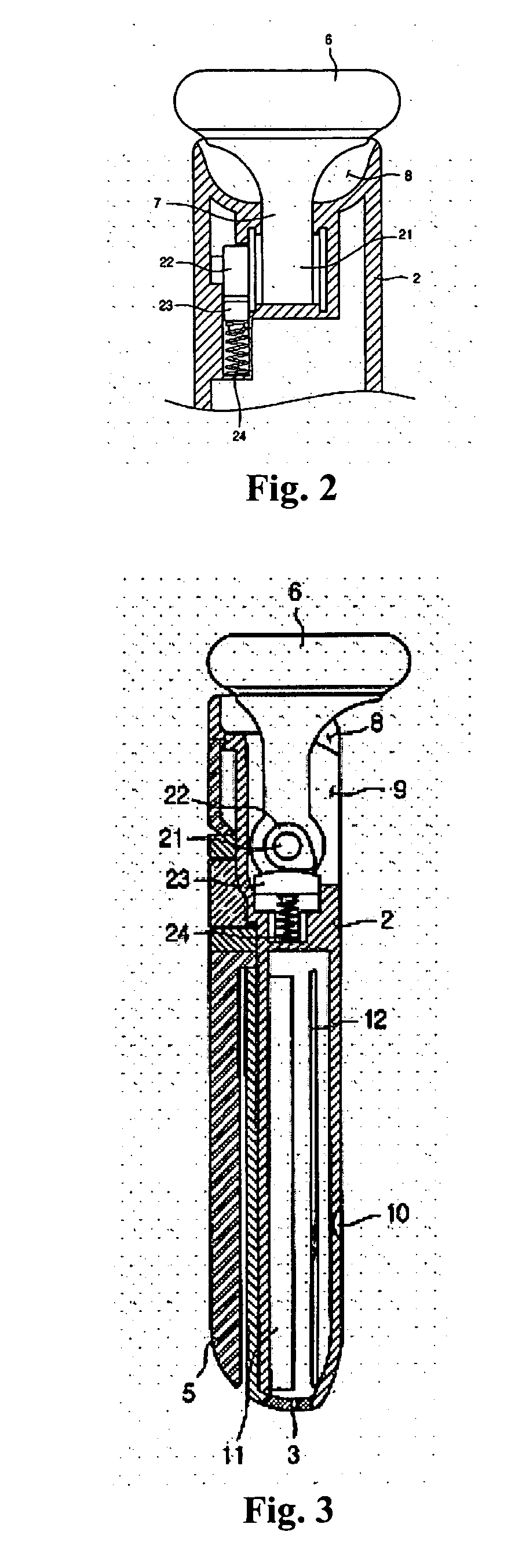
[0067]FIG. 1 is a perspective view illustrating a wireless headset 1 of the invention, FIG. 2 is a cross-sectional view taken along the line II-II′ of FIG. 1, and FIG. 3 is a cross-sectional view taken along the line I-I′ of FIG. 1.

[0068] Referring to FIGS. 1 to 3, the wireless headset 1 of the invention includes a body 2 in the form of an elongated bar and an earphone 6 mounted on the upper end of the body 2 such that it can rotate. A user can easily operate the wireless headset 1 by holding the body 2 with one hand and manipulating the earphone 6 with the fingers of the hand.

[0069] On the exterior of the body 2, the headset 1 also includes a volume controller 4 by which the user can control the volume, a clip 5 for allowing the user to easily attach the wireless headset 1, a microphone 3 for converting the user's voice into electrical signals and an on / off button 10 used for powering on or off the wireless headset 1. In addition, a charging terminal (not shown) for charging a ba...

embodiment 2

[0100] This embodiment of the invention is substantially the same as the first embodiment except that a location guide structure for the earphone has different features. Accordingly, the same parts will not be described but can be understood with reference to the first embodiment. In the drawings, the same reference numerals are used to designate like elements throughout.

[0101]FIGS. 7 and 8 are vertical cross-sectional views illustrating the wireless headset according to the second embodiment of the invention, in which the cross section of the wireless headset is cut at the same angle as in FIGS. 2 and 3.

[0102] Referring to FIGS. 7 and 8, the earphone location guide structure of this embodiment is similar to the hinge structure for the folding cover of a folding-type mobile phone, or flip-phone. The earphone location guide structure has an elastic hinge 30 at a joint between the extender 7 and the body 2.

[0103] The structure of the elastic hinge 30 will now be described. The elas...

embodiment 3

[0106] The third embodiment of the invention is substantially the same as the first embodiment except that a location guide structure for the earphone has different features. Accordingly, the same parts will not be described but can be understood with reference to the first embodiment. In the drawings, the same reference numerals are used to designate like elements throughout.

[0107]FIGS. 9 and 10 are vertical cross-sectional views illustrating a wireless headset according to the third embodiment of the invention, in which the cross section of the wireless headset is cut at the same angle as in FIGS. 2 and 3.

[0108] Referring to FIGS. 9 and 10, the earphone location guide structure of this embodiment includes an elastic hinge at a joint between the extender 7 and the body 2.

[0109] The structure of the elastic hinge will be described in detail. The elastic hinge of this embodiment includes a rotating shaft 51 formed at the lower end of the extender 7, a rotation guide 52 adapted to ...


PUM


Abstract

A foldable wireless headset is introduced comprising an elongated bar-shape main body, a hinged earphone attached at the proximal end of the main body, and an earphone position guidance for maintaining the earphone stationary at the selected position with respect to the main body either one of an extending position, retracting position and intermediate position. The wireless headset enhances operational stability, saves manufacturing costs, is easily carried, and is convenient to use. Also, the wireless headset can be automatically turned on and off in response to the extraction and retraction of the earphone.

Description

BACKGROUND OF THE INVENTION [0001] 1. Field of the Invention [0002] The present invention relates to a wireless headset, in particular, one which is separated from a main body for transmitting / receiving wireless signals, and designed to convert a wireless signal received from the main body into sound waves, such that a user is not restricted by cords but can use both hands freely while listening via the headset. The invention also relates to a control method of the same wireless headset. [0003] 2. Description of the Prior Art [0004] As generally known in the art, separate wireless headsets have become commonly used as accessories for electronic devices such as mobile phones and MP3 players. By using such a wireless headset, a user can use an electronic device such as a mobile phone or an MP3 player without having to hold it in his or her hand. The usage of such a wireless headset has been enabled by the development of local wireless communication technologies such as Bluetooth, Wire...

Claims


Application Information

Patent Timeline
IPC IPC(8): H04R25/00
CPCH04M1/05H04M1/6066
Inventor LEE, YOUNG-SOON
Owner SIMPLEBE
Why Eureka
Try Eureka