Security identification system

a security identification and system technology, applied in the field of security identification systems, can solve the problems of inability to accurately recognize faces of people at checkpoints, difficulty in the system to accurately recognize faces, incomplete recognition or identification, etc., and achieve the effect of improving the quality of the facial image of the subj

Inactive Publication Date: 2007-06-14
PELCO INC
View PDF44 Cites 106 Cited by
  • Summary
  • Abstract
  • Description
  • Claims
  • Application Information

AI Technical Summary

Benefits of technology

[0011] The present invention overcomes the above-described drawbacks by providing an interactive real-time facial recognition system which detects the presence of a subject at the checkpoint, interactively instructs the subject to stop and move into position for proper identification/recognition, analyzes the facial features of the subject as (s)h

Problems solved by technology

Manual identification of persons at a checkpoint is a slow and cumbersome process, and because it is not precise, manual identification may allow unwanted or undesirable individuals to avoid detection through disguises.
In order for a system to function properly, it is important that the system receive a clear video image of the subject's face without heavy shadows or overexposed areas that may hide critical facial features and thereby make it difficult for the system to accurately recognize faces.
However, all of these patents suffer from the drawback that unless the facial image is properly positioned and lighted for a sufficient length of time, the recognition or identification may be incomplete, inaccurate or may not take place at all.
However, neither of these patents discloses interactively instructing the subject for proper positioning, nor do they disclose any way to compensate for inadequate lighting.
If the cameras at the checkpoint do not get a good facial read, the user may be prompted to either reinsert the card or to push a button, causing the user to assume the picture position.
It is apparent that this system requires and relies upon properly initialized security cards, and is not suitable for identification of subjects from the general popula

Method used


Image

  • Security identification system
  • Security identification system
  • Security identification system

Examples


Embodiment Construction

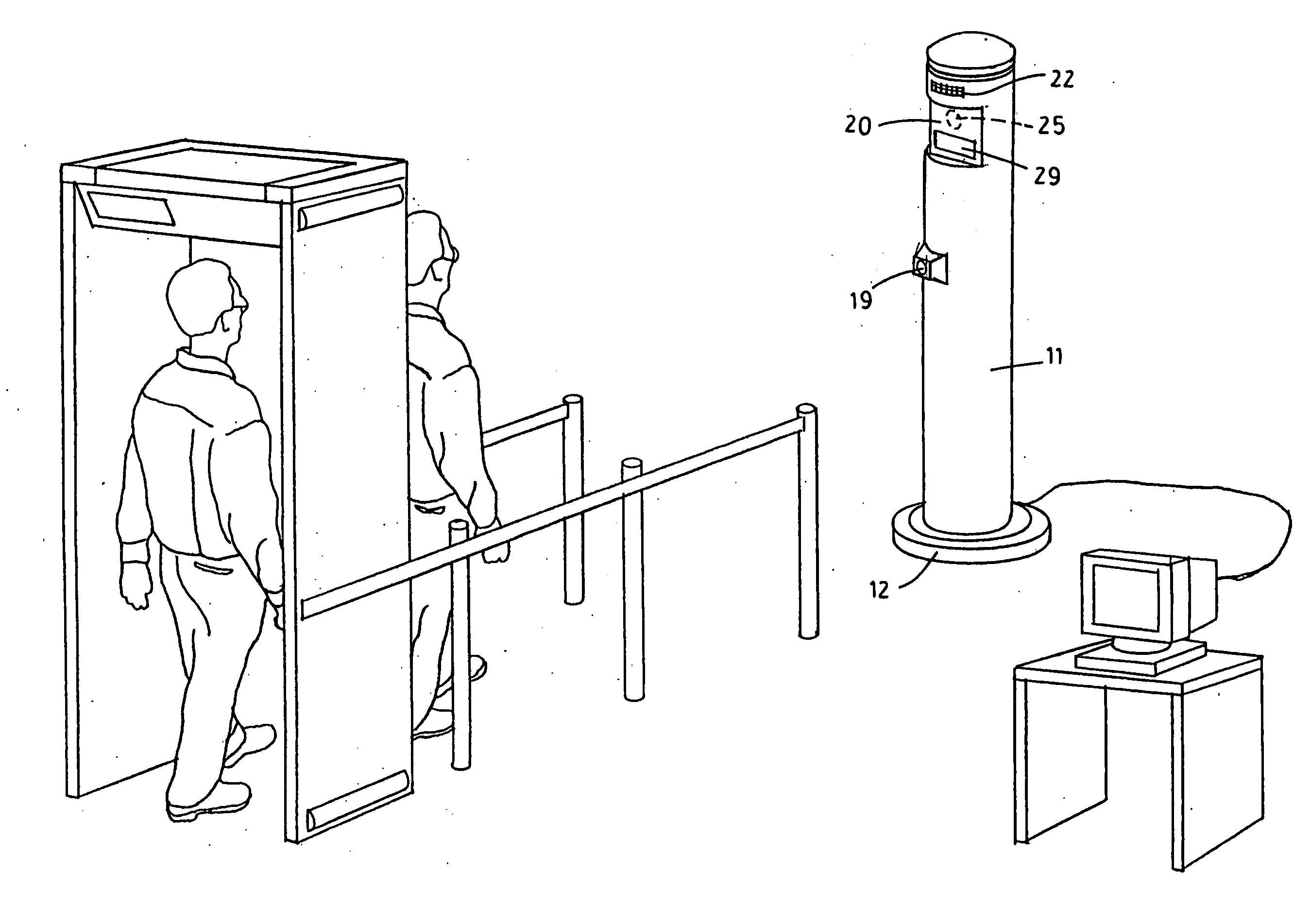
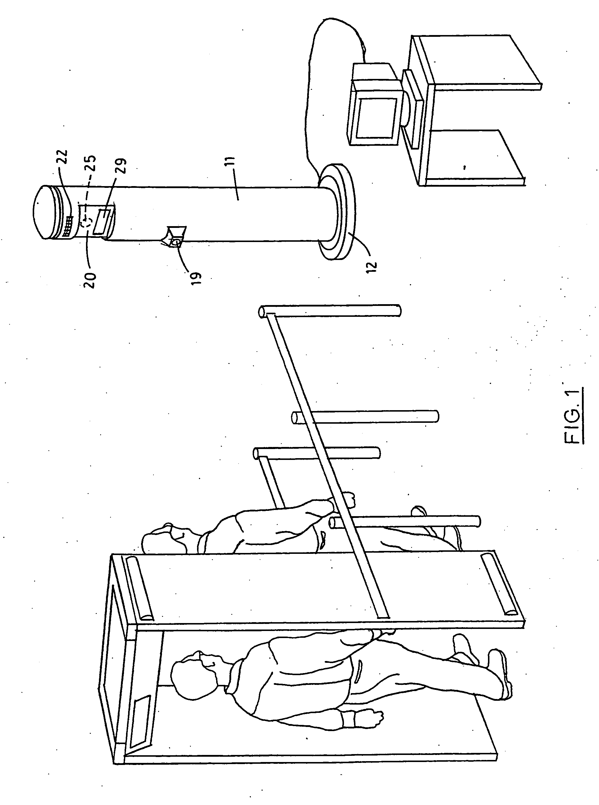
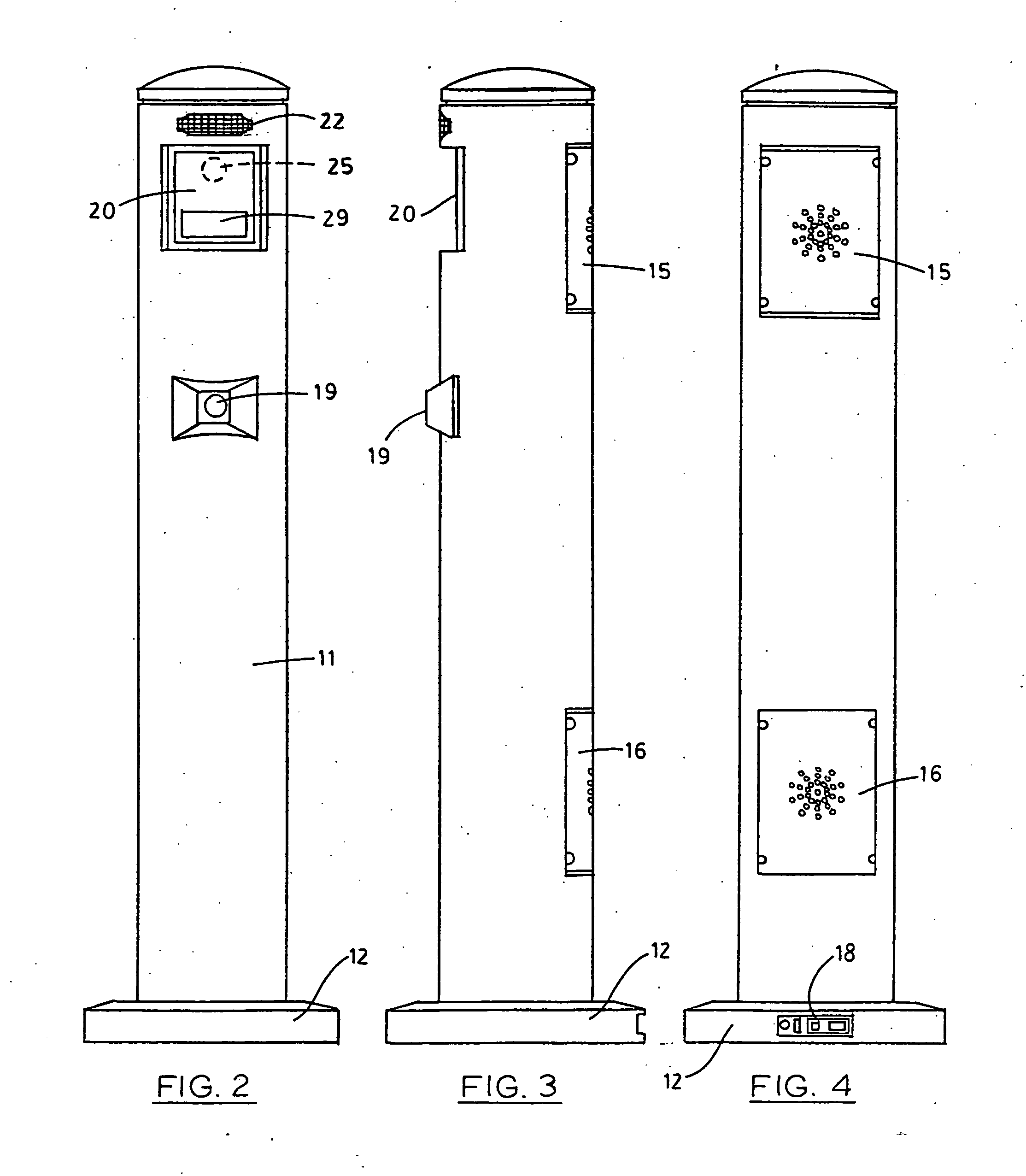
[0056] Referring to the drawings wherein like reference characters designate like or corresponding parts throughout the several views, and referring particularly to FIGS. 1, 2, and 3, it is seen that the invention includes a large diameter vertical post 11 having a support base 12. A window 20 is provided on the front of post 11 behind which a video camera 25 is deployed, preferably a high-resolution, low-light capable digital camera. Camera 25 should be selected such that is it capable of reading the facial features of individuals from as far away as 25 feet, to as close as 1 foot.

[0057] Window 20 also includes at least two illuminatable signs 29 which display the different messages such as “stop” and “go,” as well as any other additional or alternative messages such as “look up,”“step forward,”“step back,”“proceed,” etc. It is to be appreciated that instead of displaying words in window 20, visual symbols may be used to provide instructions (e.g., the universal “do not enter” sym...


PUM


Abstract

This is a security and identification system designed to obtain improved images for use by real-time facial recognition and identification systems for screening individuals passing through secure entry or checkpoints such as airport passenger terminals, government offices, and other secure locations. The system detects the presence of a subject at the checkpoint, interactively instructs the subject to stop and move into position for proper identification and recognition, analyzes the facial features of the subject as (s)he passes through the checkpoint, and compares the features of the subject with those in a database. The system then generates different signals depending upon whether or not the subject is recognized. In one aspect of the invention, different methods and apparatus are provided for compensating for low ambient light so as to improve the quality of the facial image of the subject that is obtained.

Description

CROSS-REFERENCE TO RELATED APPLICATION [0001] This application claims benefit of U.S. Provisional Application No. 60 / 338,180 filed Nov. 8, 2001, and U.S. Provisional Application No. 60 / 354,139 filed Feb. 4, 2002, and is a continuation-in-part of application Ser. No. 10 / 281,014, filed Oct. 25, 2002.BACKGROUND OF THE INVENTION [0002] 1. Field of the Invention [0003] The present invention relates to checkpoint security, and more particularly to an improved security and identification method and system for improving image quality in a facial recognition system for use in screening and / or identifying individuals passing through secure entry or checkpoints such as airport passenger terminals, government offices, office buildings, military facilities, laboratories, and other secure locations. It will be understood that the system and method disclosed herein can be used in improving image quality in other camera systems as well. [0004] 2. Description of the Prior Art [0005] Recent national ...

Claims


Application Information

Patent Timeline
IPC IPC(8): G06K9/00G06V10/145
CPCG06K9/2036G06K9/00221G06V40/16G06V10/145
Inventor WAEHNER, GLENN C.KALOCSAI, PETER
Owner PELCO INC
Why Eureka
Try Eureka