
Coexistence system and method for wireless network devices

a wireless network and coexistence technology, applied in power management, wireless commuication services, high-level techniques, etc., to achieve the effect of reducing signal interference and reducing signal power

Active Publication Date: 2007-06-14
MARVELL ASIA PTE LTD
View PDF9 Cites 193 Cited by
  • Summary
  • Abstract
  • Description
  • Claims
  • Application Information

AI Technical Summary

Benefits of technology

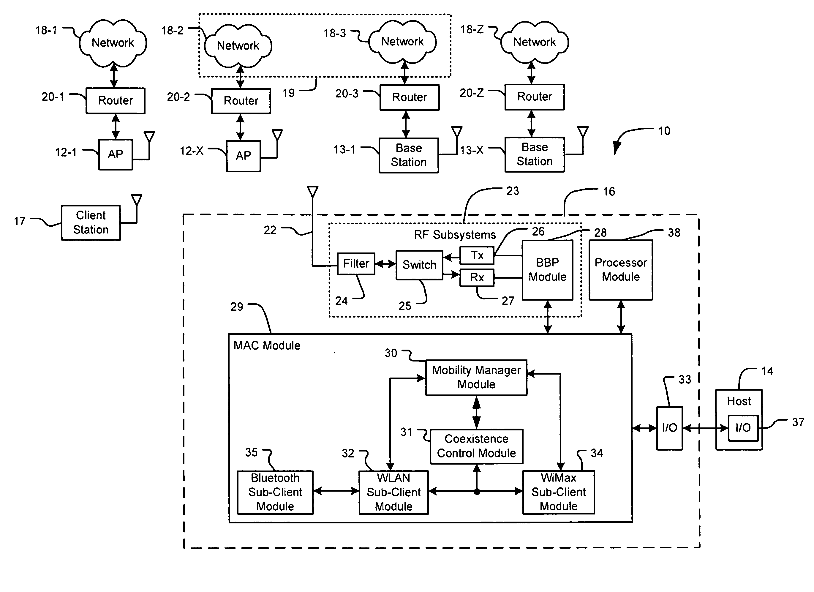
[0009] In other features, the component comprises at least one of an antenna and a radio frequency (RF) subsystem. The RF subsystem comprises at least one of a filter, a switch, a transmitter (Tx), a receiver (Rx), and a base band processor (BBP) module. The first sub-client module selectively reduces signal power to decrease signal interference with signals from the second sub-client module.
[0027] The component means comprises at least one of antenna means for receiving signals and RF subsystem means for processing the signals. The RF subsystem means comprises at least one of filter means for filtering the signals, switch means for forwarding the signals, transmitter means for transmitting the signals, receiver means for receiving the signals, and base band processor means for processing a base band of the signals. The first sub-client means selectively reduces signal power to decrease signal interference with signals from the second sub-client means.

Problems solved by technology

Further, WiMAX, WiFi, and Bluetooth may use the same frequency or nearby frequencies, which may cause interference.

Method used


Image

  • Coexistence system and method for wireless network devices
  • Coexistence system and method for wireless network devices
  • Coexistence system and method for wireless network devices

Examples


Embodiment Construction

[0059] The following description is merely exemplary in nature and is in no way intended to limit the disclosure, its application, or uses. For purposes of clarity, the same reference numbers will be used in the drawings to identify similar elements. As used herein, the term module, circuit and / or device refers to an Application Specific Integrated Circuit (ASIC), an electronic circuit, a processor (shared, dedicated, or group) and memory that execute one or more software or firmware programs, a combinational logic circuit, and / or other suitable components that provide the described functionality. As used herein, the phrase at least one of A, B, and C should be construed to mean a logical (A or B or C), using a non-exclusive logical or. It should be understood that steps within a method may be executed in different order without altering the principles of the present disclosure.

[0060] The present disclosure includes a coexistence system and method for wireless network devices with ...


PUM


Abstract

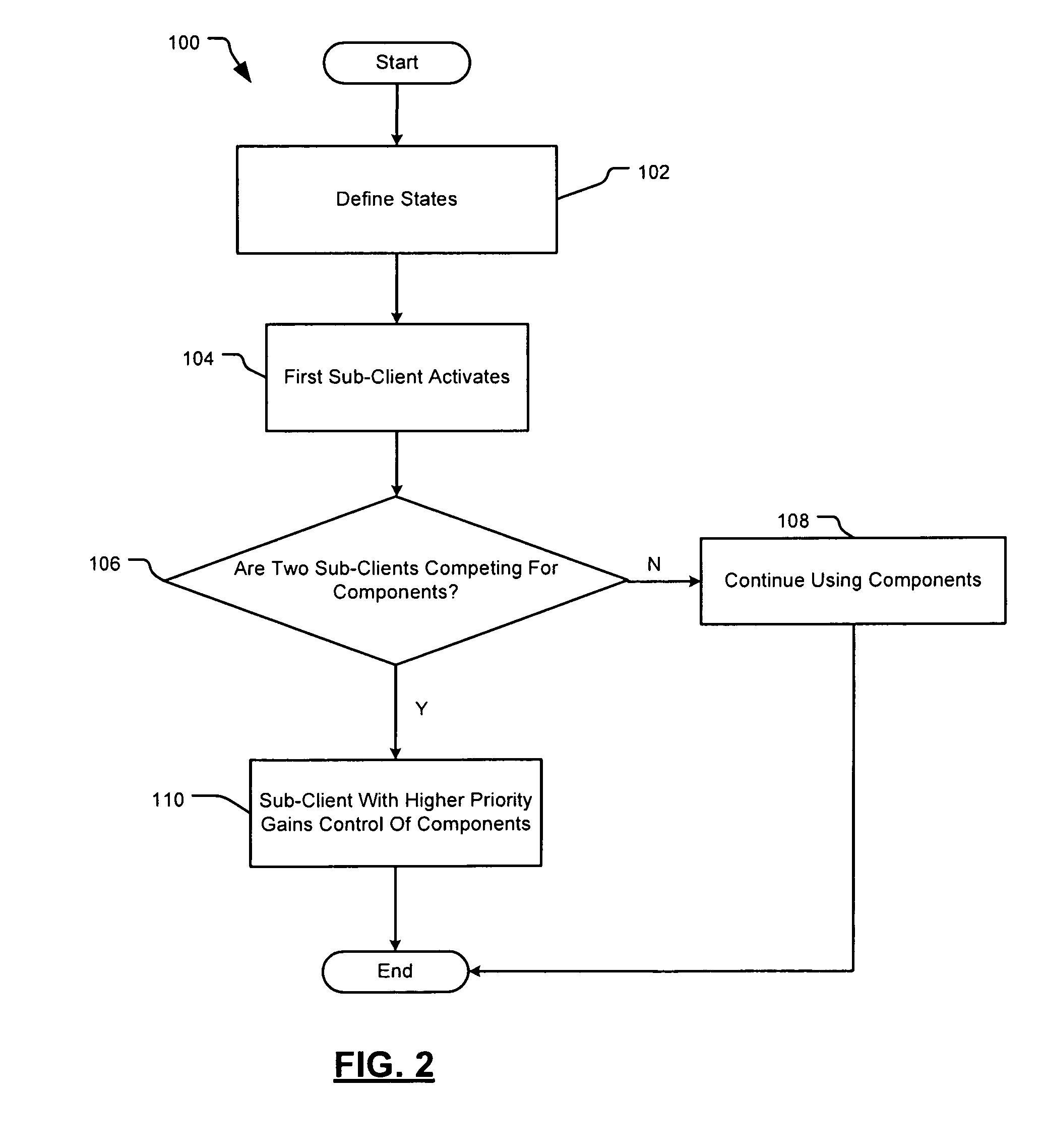
A wireless network interface includes a component, a first sub-client module that operates using a first wireless protocol, and a second sub-client module that operates using a second wireless protocol. The first and second wireless protocols are different. The first and second sub-client modules share use of the component. A component sharing control module selectively transitions the first sub-client module into and out of a state to allow the second sub-client module to use the component during the state.

Description

CROSS-REFERENCE TO RELATED APPLICATIONS [0001] This application claims the benefit of U.S. Provisional Application Nos. 60 / 748,937, filed on Dec. 9, 2005 and 60 / 808,077, filed on May 24, 2006. The disclosure of the above application is incorporated herein by reference in its entirety.FIELD OF THE DISCLOSURE [0002] The present disclosure relates to wireless network devices, and more particularly to a coexistence system for wireless network devices having multiple wireless sub-clients that share components. BACKGROUND OF THE DISCLOSURE [0003] In a Wireless Local Area Network (WLAN), client stations can communicate with other client stations in an ad hoc mode or with an access point (AP) in an infrastructure mode. WLANs typically have a range in the hundreds of feet. The client stations typically include a wireless network interface that is associated with a host device. The host device can be a desktop computer, a personal digital assistant (PDA), a mobile phone, a laptop, a personal ...

Claims


Application Information

Patent Timeline
IPC IPC(8): H04M1/00
CPCH04W88/06H04W72/0446H04W92/02H04W92/20H04W76/026H04W28/04H04W84/12H04W36/30H04W52/0225H04W52/0238H04W52/0212H04W72/1215H04W76/16Y02D30/70H04W36/302H04B7/2612
Inventor BANERJEA, RAJAGOEL, SANDESHKOPIKARE, MILIND
Owner MARVELL ASIA PTE LTD
Learn More