Ported shroud with filtered external ventilation

Active Publication Date: 2007-06-21
GARRETT TRANSPORATION I INC
View PDF14 Cites 11 Cited by
  • Summary
  • Abstract
  • Description
  • Claims
  • Application Information

AI Technical Summary

Benefits of technology

[0007] In various embodiments, the present invention solves some or all of the needs mentioned above, typically providing a turbocharger system that can extend the flow range of a compressor without introducing significant inefficiencies from recirculated bypass air.
[0008] The invention typically provides a turbocharger system having a compressor wheel including blades that define an inducer and an exducer. A compressor housing is configured to receive the compressor wheel, and defines an impeller passage within which air is to be compressed by the blades. The compressor housing has an intake port configured to provide intake air to the inducer, and a bypass port opening into the impeller passage between the inducer and exducer. The bypass port places the impeller passage in fluid communication with the atmosphere without having a fluid interaction with the intake air. Advantageously, the bypass port provides for an extended compressor flow range without introducing significant inefficiencies from recirculated bypass air.
[0009] The invention typically further features a filter adapted to filter air passing between the bypass port and the atmosphere. This bypass-air filter may be unitary with an intake-air filter, which is contained in a housing configured to operably isolate these two portions of the filter to operate as two separate filters. Advantageously, such a configuration reduces the cost of construction and maintenance.

Problems solved by technology

“Surging” occurs when a compressor operates at a relatively low flow rate with respect to the compressor pressure ratio, and the resulting flow of air throughout the compressor becomes unstable.
While a ported shroud extends the operating range of a compressor, it also creates a systemic inefficiency.
This heated recirculation flow increases the temperature of air entering the inducer, increasing the work needed from the turbine to compress the air, and thereby reducing the compressor efficiency.

Method used


Image

  • Ported shroud with filtered external ventilation
  • Ported shroud with filtered external ventilation
  • Ported shroud with filtered external ventilation

Examples


Embodiment Construction

[0016] The invention summarized above and defined by the enumerated claims may be better understood by referring to the following detailed description, which should be read with the accompanying drawings. This detailed description of particular preferred embodiments of the invention, set out below to enable one to build and use particular implementations of the invention, is not intended to limit the enumerated claims, but rather, it is intended to provide particular examples of them.

[0017] Typical embodiments of the present invention reside in a vented compressor housing for a turbocharger, along with associated methods and apparatus. Preferred embodiments of the invention are assemblies that provide for filtered venting of an impeller passage in which a compressor wheel rotates.

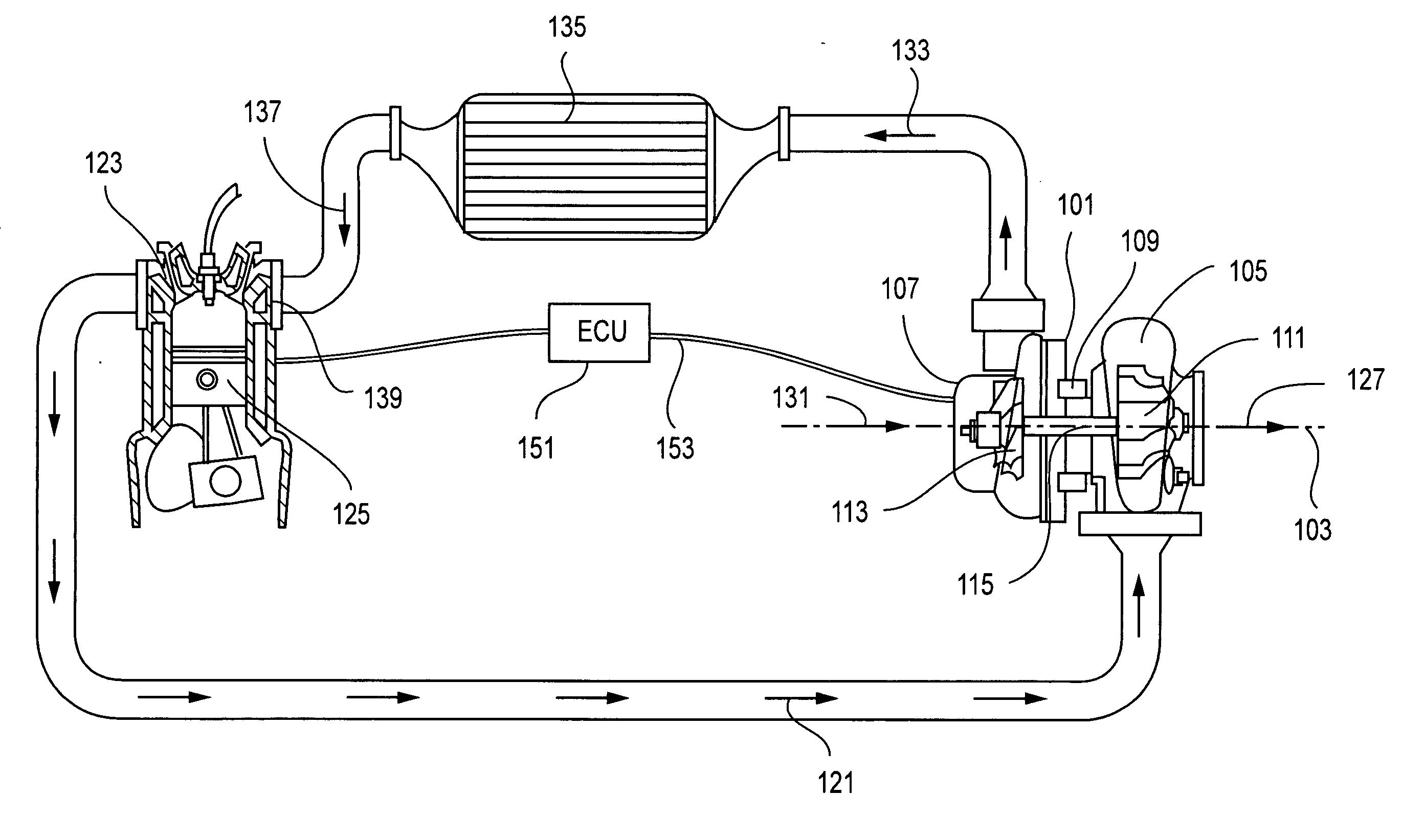
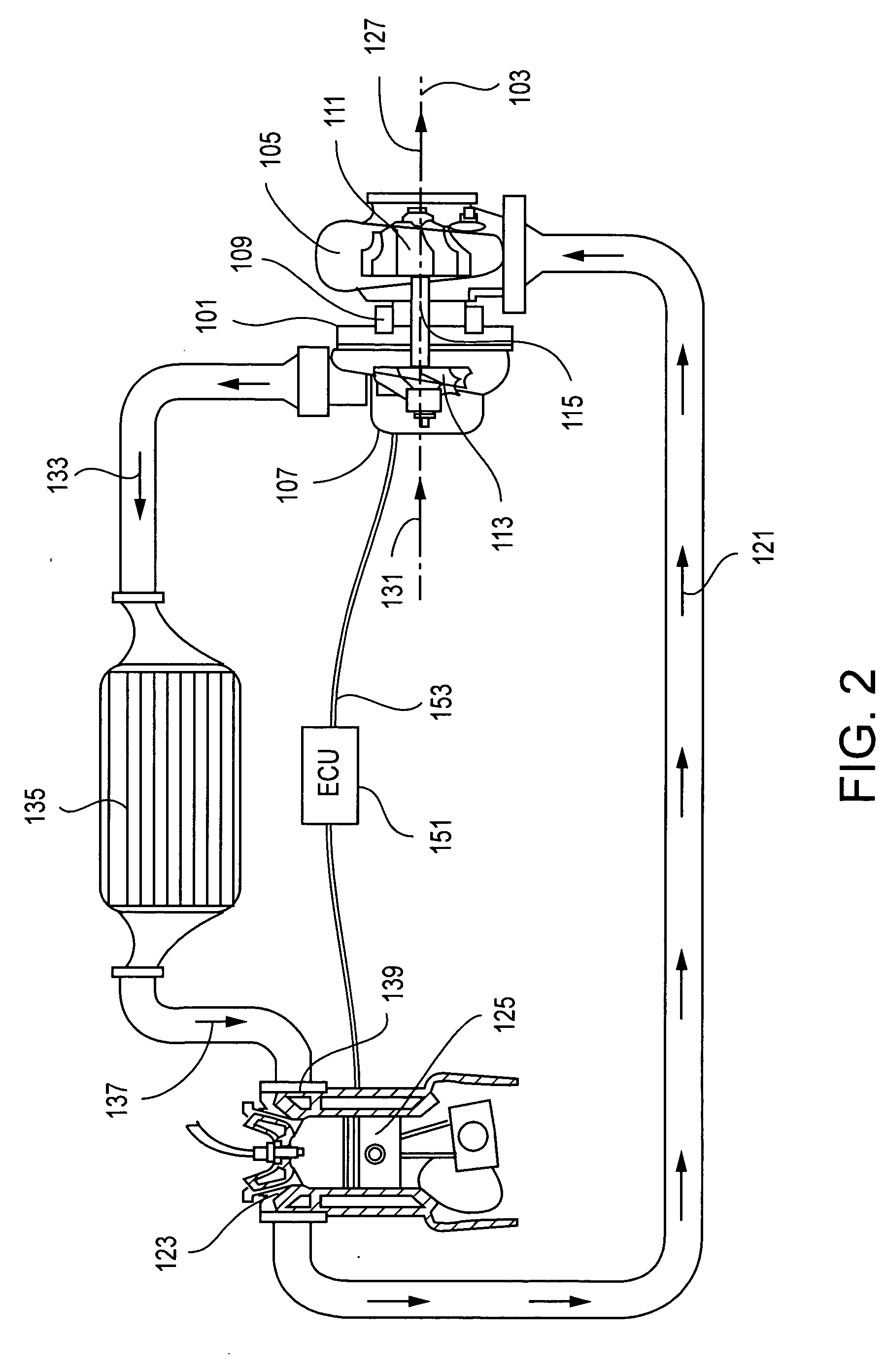
[0018] With reference to FIG. 2, in a first embodiment of the invention, a turbocharger 101 includes a turbocharger housing and a rotor configured to rotate within the turbocharger housing along an axis o...


PUM


Abstract

A turbocharger system having a compressor wheel including blades that define an inducer and an exducer, a compressor housing configured to receive the compressor wheel, and an impeller passage within which air is to be compressed by the blades, wherein the compressor housing forms an intake port configured to provide intake air to the inducer, and a bypass port opening into the impeller passage between the inducer and exducer. The bypass port places the impeller passage in fluid communication with the atmosphere without having a fluid interaction with the intake air. A bypass-air filter is adapted to filter air passing between the bypass port and the atmosphere, and is a portion of the intake-air filter.

Description

[0001] The present invention relates generally to compressors for turbomachinery and, more particularly, to apparatus and methods of ventilating a compressor chamber. BACKGROUND OF THE INVENTION [0002] Rotary compressors are used in a variety of applications for compressing gases. As an example, with reference to FIG. 1, in turbochargers a rotating compressor wheel 11 within a compressor housing 13 sucks air through an intake port 15, compresses it in an impeller passage 17, and diffuses it into a volute 19. The compressed air is supplied to an intake manifold of an internal combustion engine. The operating range of a compressor extends from a surge condition, occurring at low airflow rates, to a choke condition experienced at high airflow rates. “Surging” occurs when a compressor operates at a relatively low flow rate with respect to the compressor pressure ratio, and the resulting flow of air throughout the compressor becomes unstable. “Choking” occurs when a compressor operates a...

Claims


Application Information

Patent Timeline
IPC IPC(8): F02B33/44
CPCF04D27/0207F04D29/4213F04D29/682F04D29/684
Inventor ARNOLD, STEVEN DONCALTA, DAVID A.
Owner GARRETT TRANSPORATION I INC
Why Eureka
Try Eureka