Heat exchanger core and heat exchanger equipped therewith

a technology of heat exchanger and core, which is applied in the direction of indirect heat exchanger, laminated elements, light and heating apparatus, etc., can solve the problems of insufficient heat exchanger strength, high production cost, and unused space produced between pipe portions, etc., and achieve the effect of producing with the required strength

Inactive Publication Date: 2007-06-21
AUTOKUHLER GMBH & CO KG
View PDF7 Cites 10 Cited by
  • Summary
  • Abstract
  • Description
  • Claims
  • Application Information

AI Technical Summary

Benefits of technology

[0007] Starting from the above it is an object of the present invention to configure the heat exchanger core described above such that it can be produced with the required strength when using economical manufacturing methods.

Problems solved by technology

A disadvantage of this construction is that unused spaces are produced between the individual pipe portions and that the curved deflecting portions are generally outwit the space taken up by the actual core and are not involved in the heat exchange.
A disadvantage of this construction is, however, that either comparatively thick strips must be provided in order to produce solder faces being sufficiently large for stable soldering joints, as a result of which reduced flow cross-sections are obtained with the given overall dimensions of the core, or that, if narrow strips are used which enable favourable flow cross-sections, in return comparatively small solder faces must be accepted which are not always adequate for the required strength of the heat exchanger.
Both variants incur, therefore, comparatively high production costs which are not always tolerable.

Method used


Image

  • Heat exchanger core and heat exchanger equipped therewith
  • Heat exchanger core and heat exchanger equipped therewith
  • Heat exchanger core and heat exchanger equipped therewith

Examples


Embodiment Construction

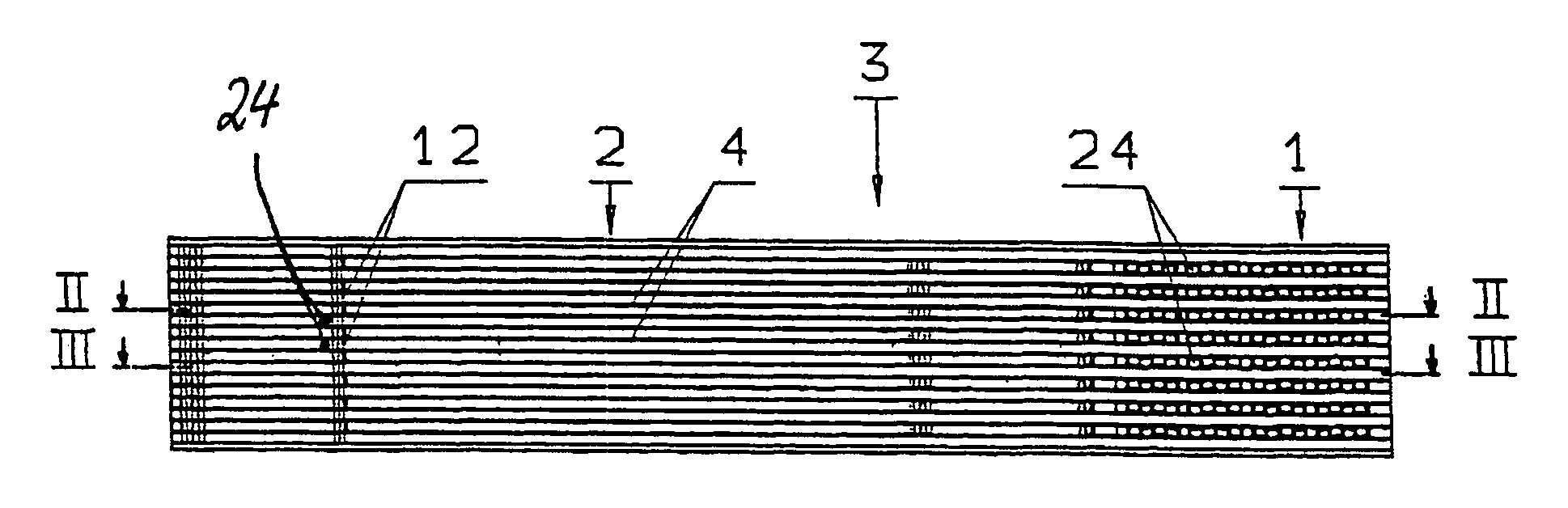
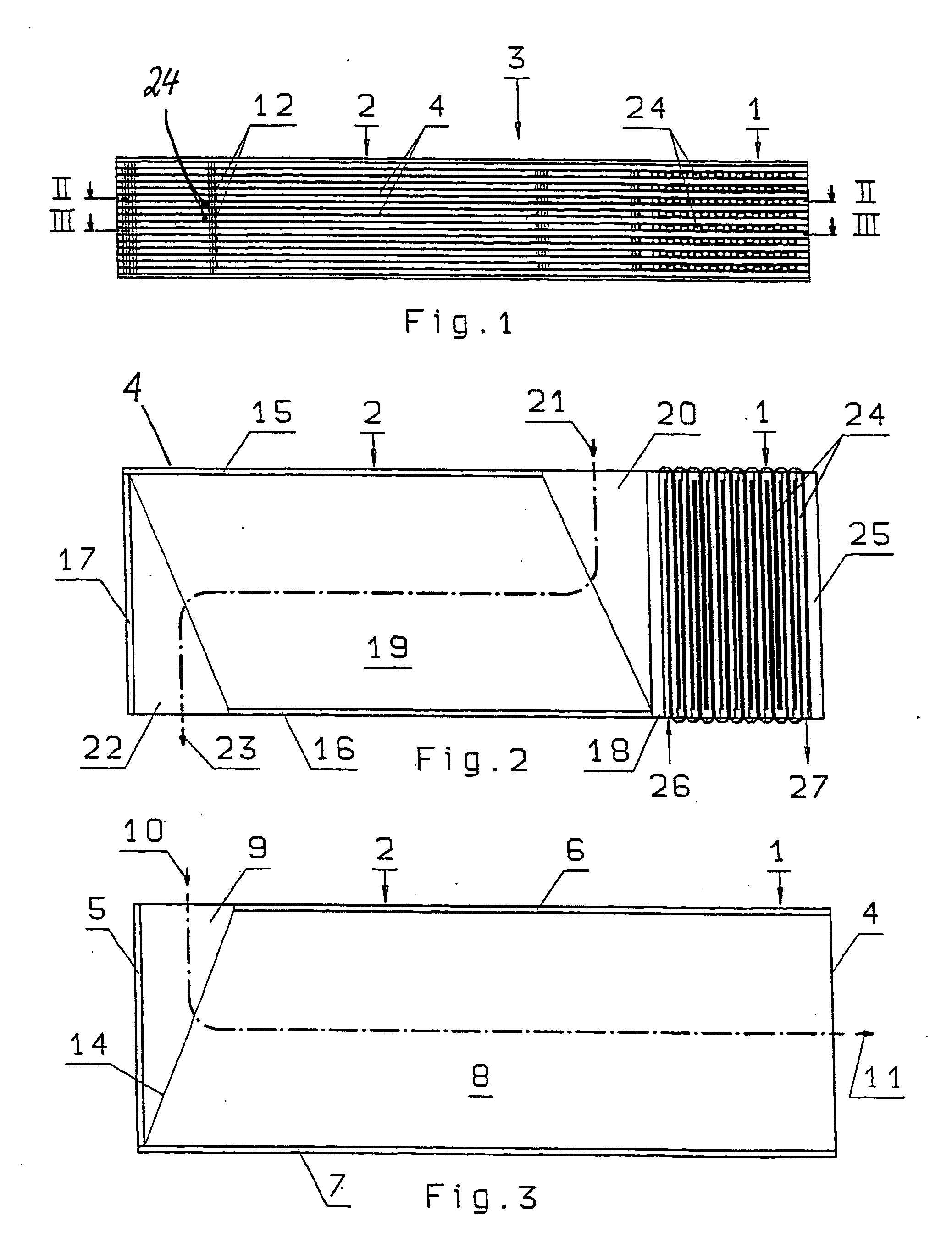
[0028] A heat exchanger device for cooling dryers in compressed air plants contains, according to FIG. 1 to 3, a coolant / air heat exchanger in the right portion and an air / air heat exchanger in the left portion. Only one coolant / air heat exchanger core 1 and, situated adjacently, one air / air heat exchanger core 2 are thereby illustrated, both being located beside each other in an assumed longitudinal direction, being combined into an integral constructional unit and forming a single, connected block 3. Of course, it would be possible also as an alternative to produce and to operate both cores 1 and 2 as separate constructional units.

[0029] The two cores 1 and 2 are mainly formed by plane-parallel, rectangular or square plates or separating metal sheets 4, respectively, which extend over the entire width and length of the block 3. According to FIG. 1 and 3, a part of the plates 4 are spaced on the one hand by strips 5 which extend perpendicular to the longitudinal direction and are ...


PUM


Abstract

A heat exchanger network has at least one passage for a coolant and a heat exchanger provided with such a core. The coolant passage has a plurality of flow channels which are disposed in parallel and delimited by separating walls and connected to each other in an undulating shape at their ends by deflection zones. The flow channels are formed by at least one lamella which has separating walls and a meandering cross-section. The deflection zones are formed by recesses which are provided at the ends of the separating walls.

Description

CROSS-REFERENCE TO A RELATED APPLICATION [0001] The invention described and claimed hereinbelow is also described in German Patent Application 20 2005 015 627.2 filed on Sep. 28, 2005. This German Patent Application, whose subject matter is incorporated here by reference, provides the basis for a claim of priority of invention under 35 U.S.C. 119(a)-(d). FIELD OF THE INVENTION [0002] The invention relates to a heat exchanger core comprising at least two plates and a passage disposed between said plates for a coolant, said passage containing a plurality of flow channels which are disposed in parallel and delimited laterally by separating walls, which are disposed perpendicular to the plates, have respectively two ends and are connected to each other in an undulating shape by deflection zones which are provided alternately at the one or other ends of the separating walls. The invention also relates to a heat exchanger comprising such a heat exchanger core. BACKGROUND OF THE INVENTION ...

Claims


Application Information

Patent Timeline
Patent Type & Authority Applications(United States)
IPC IPC(8): F28F3/00
CPCF28D9/0068F28D9/0093F28D2021/0038F28F3/025F28F2250/102F28F2250/108
Inventor GIEVERS, JOSEF
Owner AUTOKUHLER GMBH & CO KG
Why Eureka
Try Eureka