
Dual purpose blow out preventer

a blow-out preventer and dual-purpose technology, applied in the direction of drilling casings, drilling pipes, borehole/well accessories, etc., can solve the problems of increasing the risk of safety risk for those providing service and maintenance on the bop stack, increasing the capital and maintenance costs, and difficult rotational alignment of ct strings

Active Publication Date: 2007-06-21
BAKER HUGHES INC
View PDF8 Cites 62 Cited by
  • Summary
  • Abstract
  • Description
  • Claims
  • Application Information

AI Technical Summary

Benefits of technology

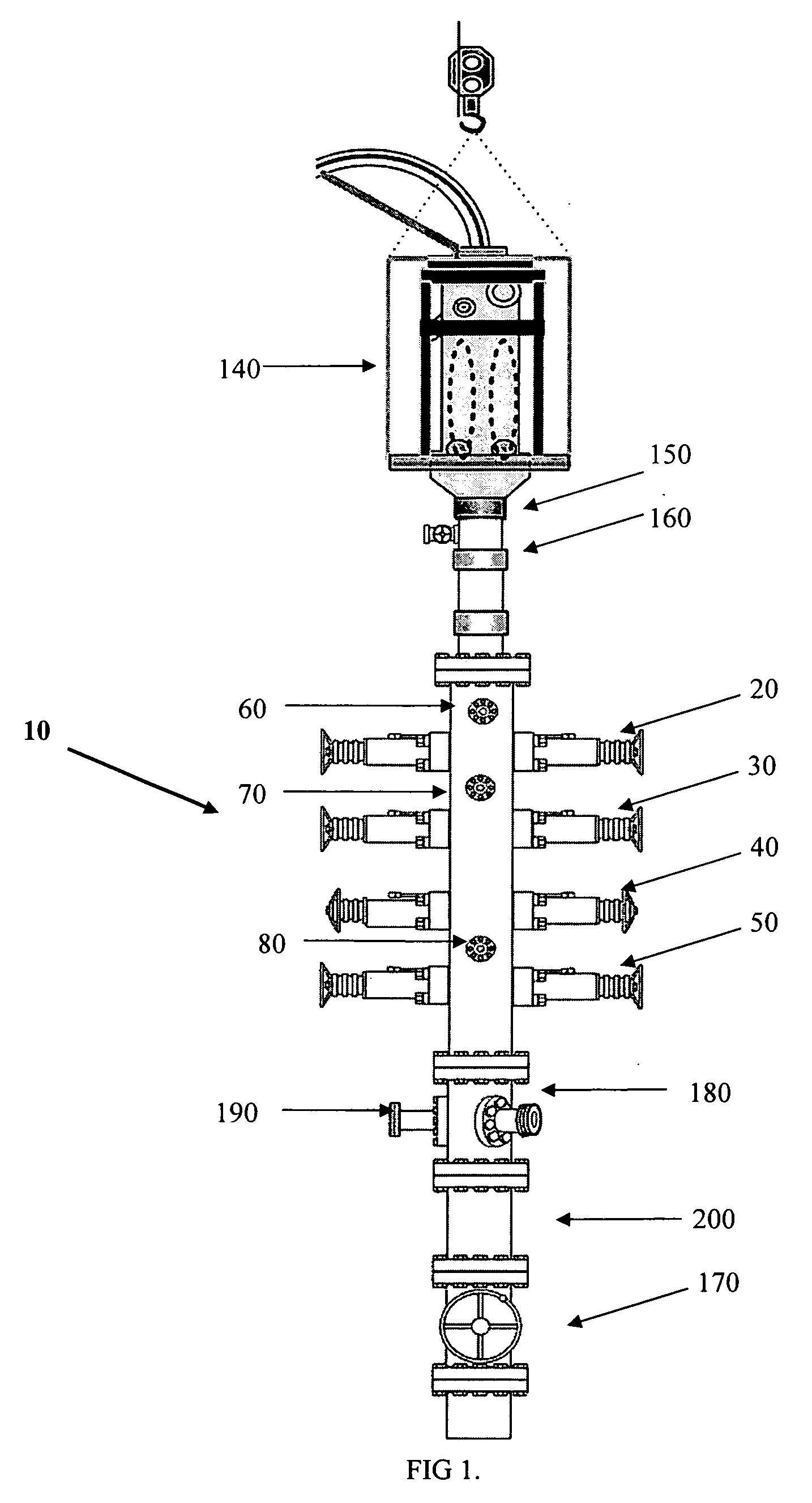
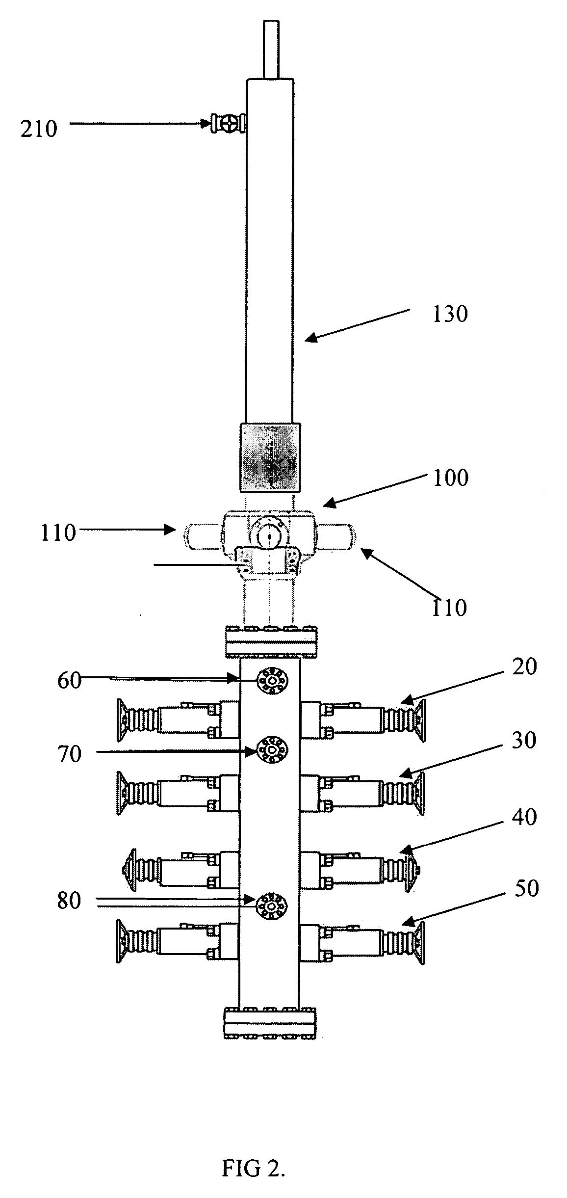
[0028] In one embodiment, the dual purpose BOP may include a first passageway located above the set of blind / shear rams that is in communication with a first valve, the first valve being a two-way valve. The first valve may be used to selectively allow pressure from above the blind / shear rams, when actuated, into a chamber located behind the blind / shear rams. The pressure within the chamber may assist the hydraulics to maintain the blind / shear rams in the actuated position sealing off against the pressure from above the blind / shear rams. The first valve may be configured to default to a closed positioned preventing pressure into the chamber behind the blind / shear rams. Hydraulic pressure may be applied to open the valve allowing pressure to enter into the chamber. In the event the valve fails, it may be configured to prevent pressure from entering into the chamber.
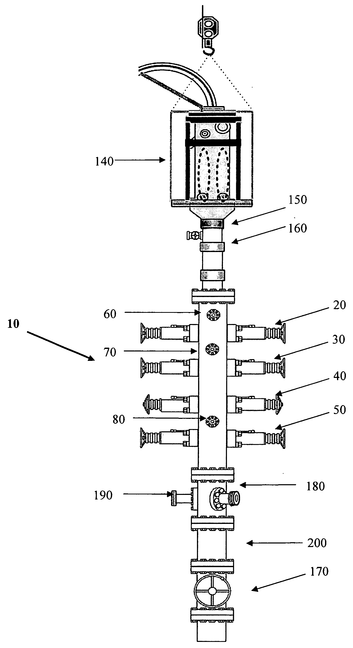
[0044] One embodiment of the present disclosure is BOP that functions as a wellhead pressure containment BOP as well as a deployment BOP for deploying a BHA using mechanically actuated connectors. In one embodiment, this is achieved by the BOP having four set of rams. The four sets of rams from the top down may be a set of blind / shear rams, a set of locate rams, a set of lock rams, and a set of pipe / slip rams. The blind / shear rams may function as a gate valve that closes off the BOP. The blind / shear rams may be bi-directional thus, being able to seal off the BOP bore from pressure above, such as when an attached apparatus is being pressure tested and the blind / shear rams may be able to seal off downhole pressure from below. In the wellhead pressure containment mode, the blind / shear rams may be able to cut through the CT string and the wireline in order drop the BHA into the well and seal off wellhead pressure in an emergency situation.

Problems solved by technology

Rotational alignment of a CT string is not easy as neither half of the connector can be easily rotated.
However, as the '652 patent recognizes, such a “deployment BOP” does not perform a standard BOP function and is actually expected to be used in combination with a wellhead pressure containment BOP.
The increased height of the BOP stack increases the safety risk to those providing service and maintenance on the BOP stack.
Further, the use of both a deployment BOP and a wellhead pressure containment BOP increases the capital and maintenance costs.
Overall, the use of a deployment BOP in addition to a wellhead pressure containment BOP increases the costs expended on the operation.
Large cranes are expensive and working with heavy suspended loads is slow and less safe than handling smaller lighter loads.
Further, it is often difficult to connect a CT string to a BHA located in the wellhead.
However, a BOP that performs these two functions may require bi-directional sealing rams.
The operation of such valves may be dangerous due to the high pressures often contained by a wellhead pressure containment BOP.

Method used


Image

  • Dual purpose blow out preventer
  • Dual purpose blow out preventer
  • Dual purpose blow out preventer

Examples


Embodiment Construction

[0058] Illustrative embodiments of the invention are described below as they might be employed in the use of designs for a dual purpose BOP or in the deployment of a tool into a dual purpose BOP. In the interest of clarity, not all features of an actual implementation are described in this specification. It will of course be appreciated that in the development of any such actual embodiment, numerous implementation-specific decisions must be made to achieve the developers' specific goals, such as compliance with system-related and business-related constraints, which will vary from one implementation to another. Moreover, it will be appreciated that such a development effort might be complex and time-consuming, but would nevertheless be a routine undertaking for those of ordinary skill in the art having the benefit of this disclosure.

[0059] Further aspects and advantages of the various embodiments of the invention will become apparent from consideration of the following description a...


PUM


Abstract

An improved dual purpose blow out preventer (“BOP”) that provides both deployment and wellhead pressure containment functions. The dual purpose BOP may include four sets of rams including a set of seal / slip rams that provide bi-directional sealing being a first barrier to downhole pressure. The seal / slip rams may also grip a portion of a bottom hole assembly and create the bottom seal of an annular chamber. The BOP may include a set of seal rams that create the top seal of the annular chamber. The annular chamber may be pressurized through a port in the BOP, which may actuate a coiled tubing connector. The BOP may include a set of locate rams used to position a coiled tubing connector within the BOP stack. The BOP may also include a set of blind / shear rams that provide bi-directional sealing being a second barrier to wellhead pressure.

Description

[0001] This application is a Non-provisional application claiming priority to U.S. Provisional Application Ser. No. 60 / 738,244 entitled, “Dual Purpose Blow Out Preventor,” by John Edward Ravensbergen, filed Nov. 18, 2005, hereby incorporated by reference in its entirety herein.BACKGROUND OF THE INVENTION [0002] 1. Field of the Invention [0003] The present invention relates generally to a dual purpose blow out preventer (“BOP”). Specifically, the BOP combines the functions of a deployment BOP with a typical wellhead pressure containment BOP. The invention is particularly useful in oil and gas well applications using a coiled tubing (“CT”) string connected to a bottom hole assembly (“BHA”) using a universal connect / disconnect (“UCD”). The invention may also be used in applications where mechanically actuated connectors are used to connect a BHA to a CT string. [0004] 2. Description of the Related Art [0005] U.S. Pat. No. 6,209,652 (“the '652 patent”), incorporated herein in its entire...

Claims


Application Information

Patent Timeline
IPC IPC(8): E21B19/22E21B33/06
CPCE21B19/22E21B33/06
Inventor RAVENSBERGEN, JOHN EDWARDBRUNSKILL, DOUG
Owner BAKER HUGHES INC
Learn More