DNA separation device, DNA separation method, and ligand DNA

a separation device and ligand technology, applied in the direction of isotope separation, diaphragm, electrolysis, etc., can solve the problems of inability to minutely control the bonding force between the sample dna b>200/b> and the marker dna b>212/b>, and require an immense amount of labor and time to estimate various, so as to achieve the effect of short tim

Inactive Publication Date: 2007-06-21
RIKEN +1
View PDF1 Cites 3 Cited by
  • Summary
  • Abstract
  • Description
  • Claims
  • Application Information

AI Technical Summary

Benefits of technology

[0024] The present invention is made to solve the above-mentioned problems and has for its object to provide a DNA separation device and a DNA separation method which can separate a sample DNA appropriately in short time, and can deal with various kinds of target sample DNAs, without the necessity of searching for an optimum electrophoresis condition by complicatedly combining the amount of a bonding control agent to be contained in the conjugate DNA, the viscosity of linear polymer, the amount of the sample DNA, the amount of the conjugate DNA, and the like, for each DNA sequence as a detection target in the sample DNA, when separating the sample DNA by electrophoresis.

Problems solved by technology

In this method, however, the bonding force between the sample DNA 200 and the marker DNA 212 cannot be minutely controlled.
However, as described above, it requires an immense amount of labor and time to estimate various patterns in which the amount of the bonding control agent included in the conjugate DNA, the viscosity of the non-electrophoresis material 211, the amount of the sample DNA 200, and the amount of the conjugate DNA 210 are complicatedly combined for each sample.

Method used


Image

  • DNA separation device, DNA separation method, and ligand DNA
  • DNA separation device, DNA separation method, and ligand DNA
  • DNA separation device, DNA separation method, and ligand DNA

Examples


embodiment 1

[0063] In a first embodiment of the present invention, a first ligand DNA that can be bonded to both a first sample DNA and a conjugate DNA, and a second ligand DNA that can be bonded to both a second sample DNA and the conjugate DNA are bonded to the first sample DNA and the second sample DNA to create a first DNA complex and a second DNA complex, respectively, and thereafter, the first and second DNA complexes are made to perform electrophoresis in the conjugate DNA to separate these DNA complexes.

[0064] Hereinafter, a description will be given of the constructions of the conjugate DNA and the ligand DNAs according to the first embodiment.

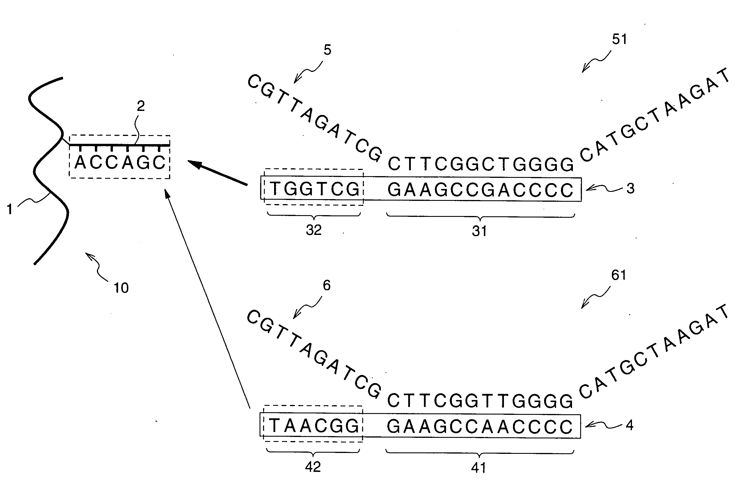
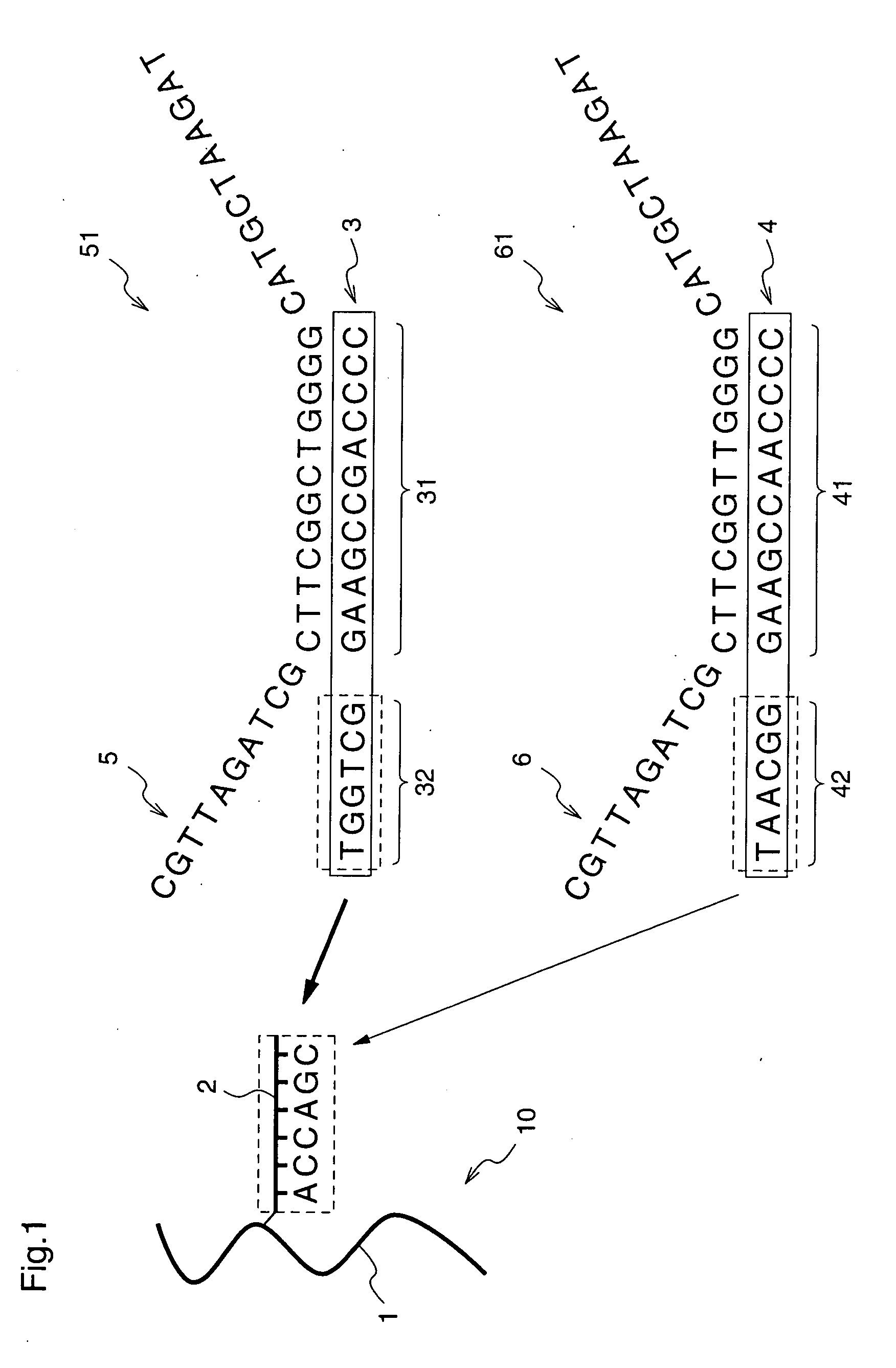
[0065]FIG. 1 is a diagram illustrating the correlations among the conjugate DNA, the two sample DNAs included in a sample solution, and the two ligand DNAs, according to the first embodiment.

[0066] Initially, the conjugate DNA 10 according to the first embodiment is formed by bonding a non-electrophoresis material 1 and a marker DNA 2 as in th...


PUM

PropertyMeasurementUnit
lengthaaaaaaaaaa
inner diameteraaaaaaaaaa
lengthaaaaaaaaaa

Abstract

A ligand DNA including a probe portion having a sequence that is complementary to a target DNA to be detected in a sample DNA, and a probe portion having a base sequence that is complementary to a base sequence of a marker DNA 2 in a conjugate DNA 10 is formed, and the sample DNA and the ligand DNA are combined to form a DNA complex, and further, the DNA complex is made to perform electrophoresis in the conjugate DNA. Therefore, it is possible to provide a DNA separation detection method which can appropriately separate the sample DNA and deal with various kinds of target sample DNAs in short time, without the necessity of searching for an optimum electrophoresis condition by complicatedly combining the amount of a bonding control agent to be contained in the conjugate DNA, the viscosity of linear polymer, the amount of the sample DNA, the amount of the conjugate DNA, and the like, for each DNA sequence as a detection target, when separating the sample DNA by electrophoresis.

Description

FIELD OF THE INVENTION [0001] The present invention relates to a DNA separation device and a DNA separation method for detecting a difference in portions of base sequences of DNAs, and a ligand DNA. BACKGROUND OF THE INVENTION [0002] In recent years, with rapid progress of chemical biology, the involvement of genes in various diseases has been understood with a fair degree of precision, and medical cares targeted at genes have attracted attention. [0003] With respect to DNA, currently, SNPs (which is an abbreviation of single nucleotide polymorphisms, and a general term for a difference of a single code (single base) in genes) attract attention. The reason is as follows. By classifying SNPs, it is possible to predict the prevalence rates of many diseases, and the effects or sensitivities of individuals to medical agents, and furthermore, it is possible to perform perfect identification of an individual because there absolutely exist no plural human beings having completely the same ...

Claims


Application Information

Patent Timeline
Patent Type & Authority Applications(United States)
IPC IPC(8): C07K1/26G01N27/00
CPCC12N15/101C12Q1/6827C12Q1/6837G01N27/447Y10T436/143333C12Q2565/125C12Q2535/131C12Q2525/161
Inventor HAYASHI, MIHOMORI, KAZUYOSHIMAEDA, MIZUO
Owner RIKEN
Why Eureka
Try Eureka