Vacuum breaker arrangement

a vacuum breaker and arrangement technology, applied in mechanical equipment, transportation and packaging, functional valve types, etc., can solve the problems of increasing vacuum and impairing the operation of the engine, and achieve the effect of reducing pressure, accurately positioning the valve part, and being convenient to adap

Active Publication Date: 2007-06-21
PROTECTOSEAL
View PDF12 Cites 15 Cited by
  • Summary
  • Abstract
  • Description
  • Claims
  • Application Information

AI Technical Summary

Benefits of technology

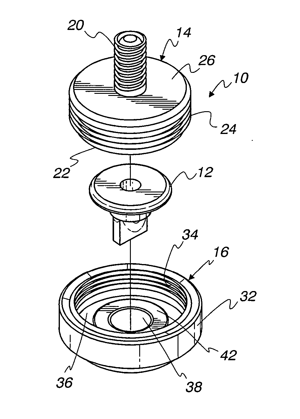
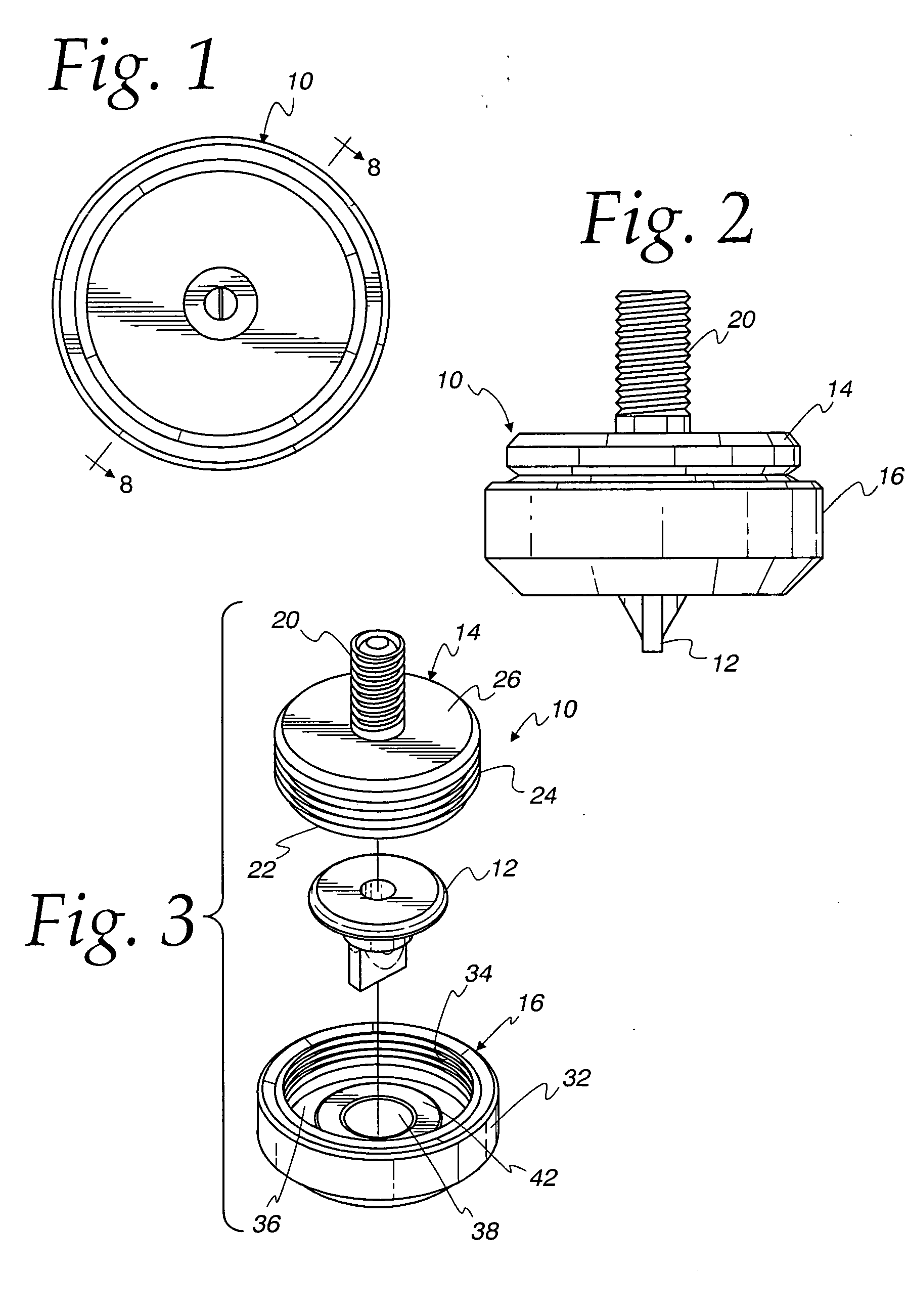
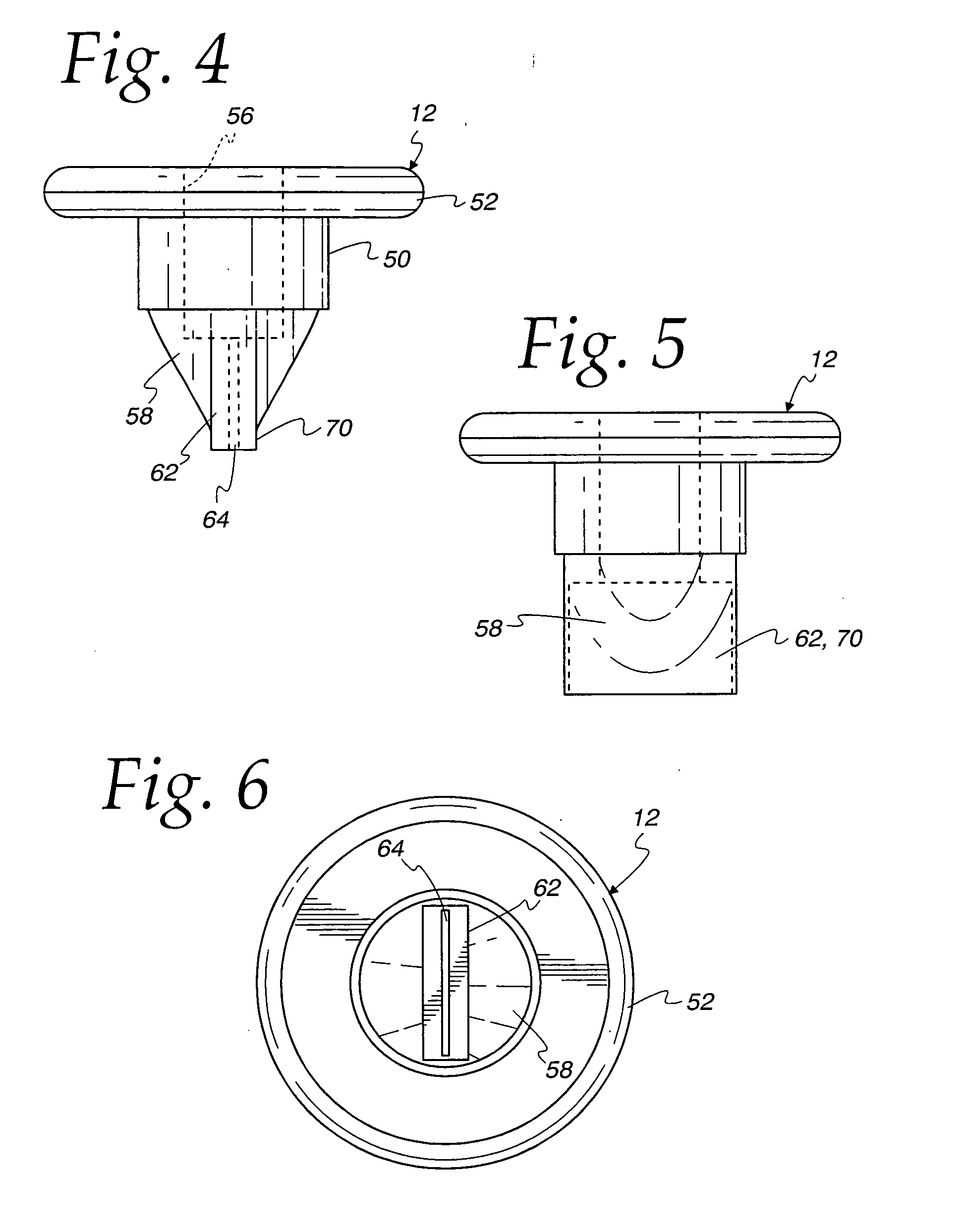
[0008] In a further aspect, the invention relates to a control member for use with a vacuum breaker for automatically controlling pressure within a container, and operable between a closed position at a first pressure and an open position at a second, reduced pressure. The control member comprises an intermediate body portion, a resiliently collapsible valve part, an enlarged head for accurately positioning the valve part with respect to an external housing and an end portion including the valve part. The intermediate body portion is disposed between the enlarged head and the end portion. The intermediate body portion and the enlarged head cooperate to define a continuous flow passageway extending through at least a major portion of the control member. The portion of the flow passageway defined by the valve part comprises a slit. In one instance, the valve part, at the first pressure, comprises an elongated slit of generally zero opening area, the slit being closed by resilient forces stored in resilient material forming the valve part. In another instance, the valve part is made of resilient material and the slit has a nonzero area when at rest, being closed in the presence of a

Problems solved by technology

As fuel in the tank is consumed during operation of the vehicle or machinery, an increasing vacuum ca

Method used


Image

  • Vacuum breaker arrangement
  • Vacuum breaker arrangement
  • Vacuum breaker arrangement

Examples


Embodiment Construction

[0028] The invention disclosed herein is, of course, susceptible of embodiment in many different forms. Shown in the drawings and described hereinbelow in detail are preferred embodiments of the invention. It is understood, however, that the present disclosure is an exemplification of the principles of the invention and does not limit the invention to the illustrated embodiments.

[0029] For ease of description, fuel tank safety equipment utilizing a vacuum breaker arrangement embodying the present invention is described below in its usual assembled position as shown in the accompanying drawings, and terms such as upper, lower, horizontal, longitudinal, etc., may be used herein with reference to this usual position. However, the fuel tank safety equipment may be manufactured, transported, sold or used in orientations other than and described and shown herein.

[0030] As will be seen herein, different types of apparatus embodying the present invention are described. Generally speaking,...


PUM


Abstract

A vacuum breaker arrangement for use with a container includes body parts holding a resilient valve member captive. The valve member includes an intermediate body part, intermediate and enlarged head and a valve part. The valve part is made of resilient material which defines an internal passageway communicating with an opening in the body parts. The valve part includes an end portion defining a slit which is closed at a first pressure and which is automatically opened at a second, reduced pressure.

Description

FIELD OF THE INVENTION [0001] The present invention relates to the field of safety equipment for the handling of volatile fluids, and in particular to vacuum breaker arrangements for use with fuel tank safety caps. BACKGROUND OF THE INVENTION [0002] Fuel tank safety caps are often provided, and are required in certain applications, to cover the fuel tank of gasoline or diesel powered vehicles or machinery. The caps must provide a secure closure for a filler neck or the like of a fuel tank, but must be readily openable, but lockable, as desired. In addition, a cap should include an automatic pressure relief mechanism to prevent pressure buildup within a fuel tank due to temperature rise of the fuel, or other factors. As fuel in the tank is consumed during operation of the vehicle or machinery, an increasing vacuum can develop within the tank which can impair operation of the engine by preventing efficient fuel flow. [0003] Accordingly, it is desirable to provide both vacuum and press...

Claims


Application Information

Patent Timeline
IPC IPC(8): B65D90/22
CPCB60K2015/03547F16K15/147F16K24/06
Inventor PIOTROWSKI, THOMAS C.MUTZBAUER, CHRISTIAN A.
Owner PROTECTOSEAL
Why Eureka
Try Eureka