

Transformable skin
- Summary
- Abstract
- Description
- Claims
- Application Information
AI Technical Summary
Benefits of technology
Problems solved by technology
Method used
Image

Examples
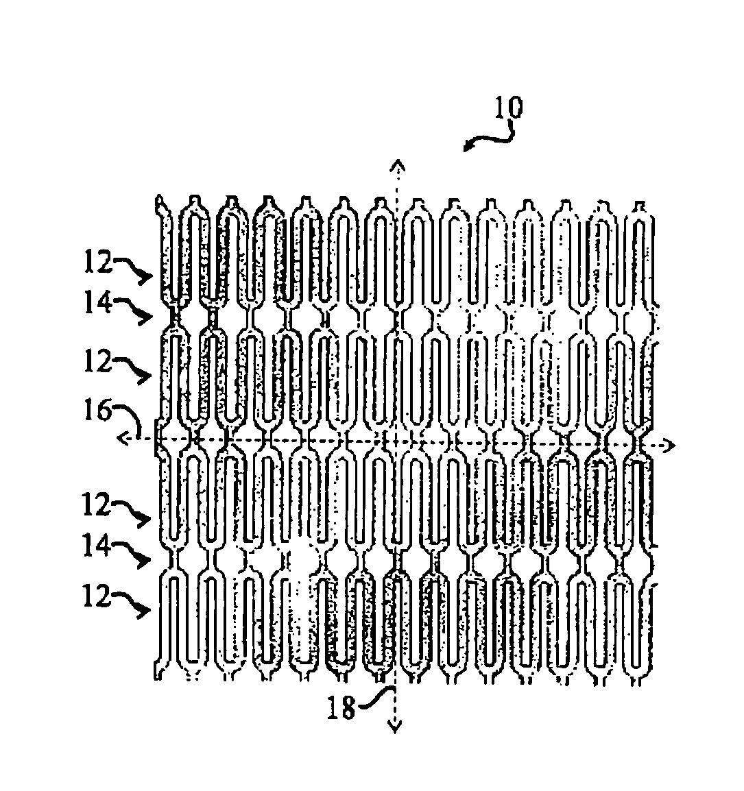
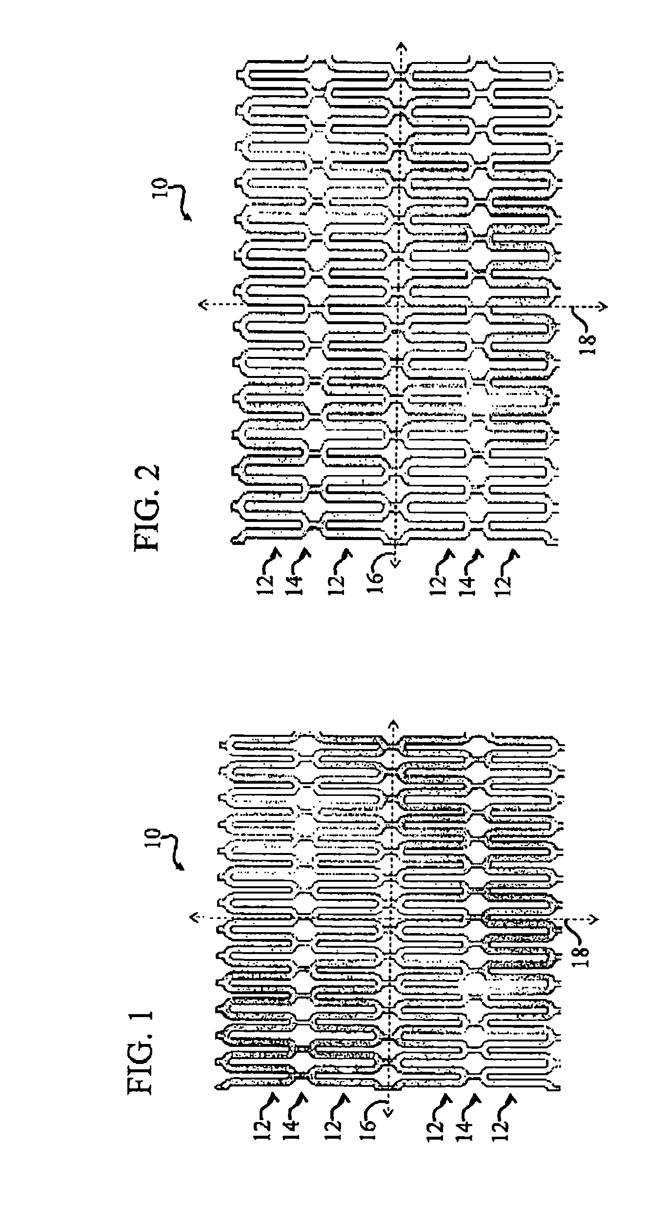
embodiment 10
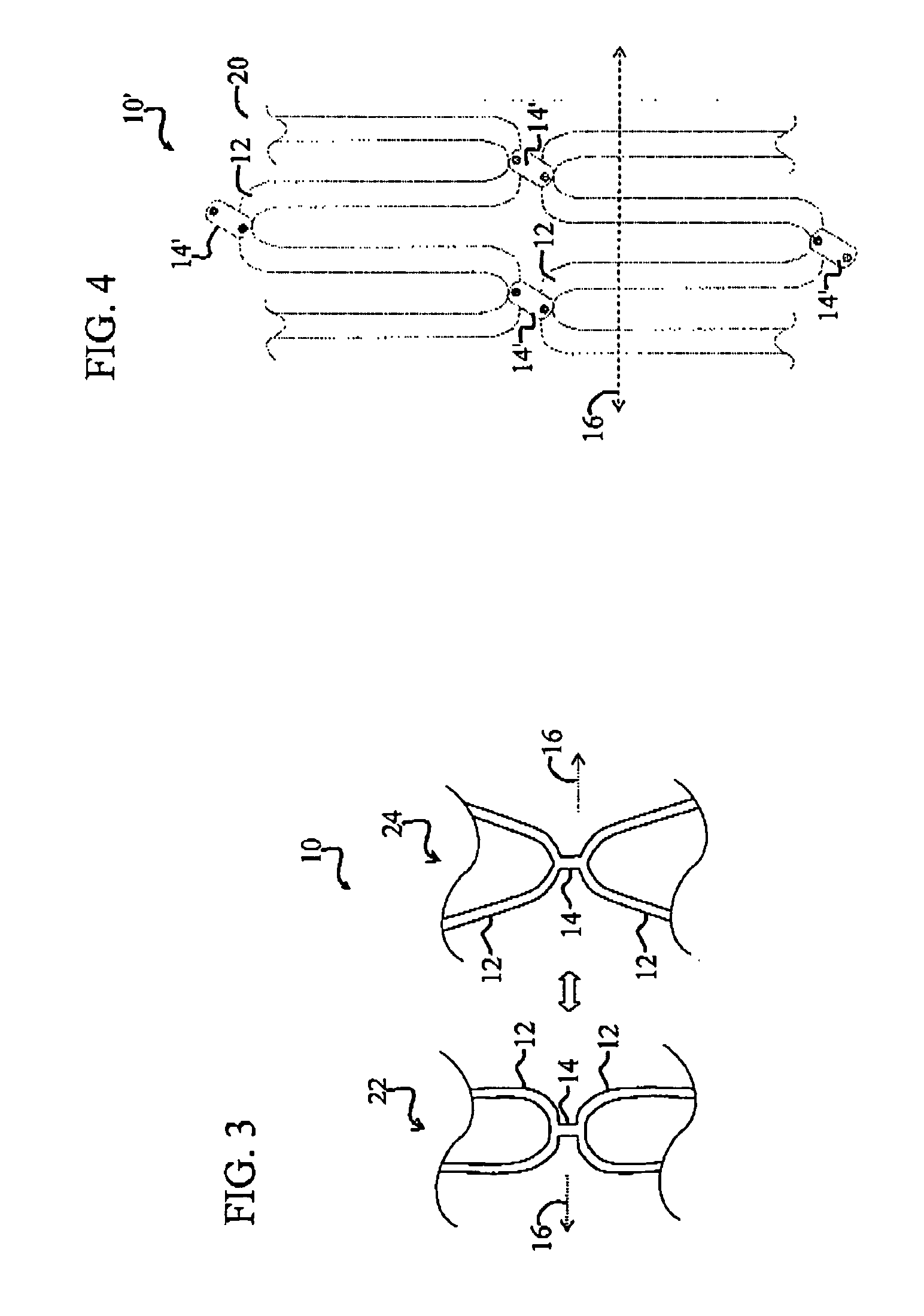
[0053]FIG. 4 is a magnified view of a first alternative embodiment 10′ of the flexible skin 10 of FIG. 1. The alternative skin 10′ of FIG. 4 is similar to the skin 10 of FIG. 1 with the exception that the connecting beams 14 shown in FIG. 1 are replaced with pivoting connecting structures 14′ in FIG. 4. Furthermore, the flexible skin 10′ includes an elastomeric skin coating 20 that coats the springs 12 and accompanying pivoting connecting structures 14′. Unlike the skin 10 of FIG. 1, the skin 10′ facilitates horizontal shear deformation when the springs 12 remain maximally compressed.
[0054] The pivoting connecting structures 14′ are pivotally connected between adjacent springs 12. These pivoting connecting structures 14′ facilitate horizontal shear deformation. The pivot connectors that connect the pivoting connecting structures 14′ to the partially-planar springs 12 may be readily constructed by those skilled in the art via well-known MicroElectroMechanical Systems (MEMS) processes...
embodiment 30
[0059]FIG. 5 is a diagram of an alternative embodiment 30 of the flexible skin of FIG. 1. The alternative flexible skin 30 lacks springs but includes vertical nickel titanium rods or connecting beams 32 that are pivotally connected in parallel between a top horizontal beam 34 and a bottom horizontal beam 36. The vertical connecting beams 32 are pivotally connected to the horizontal beams 34, 36 via flexible connectors 50, as discussed more fully below. Alternatively, the vertical connecting beams 32 may be pivotally connected to the horizontal beams 34, 36 via other pivoting connectors, such as MEMS pivot connectors similar to the connecting beams 14′ of FIG. 4.
[0060] The vertical connecting beams 32 and accompanying horizontal beams 34, 36 are covered with the elastomeric polymer 20 coating, which may include one or more layers. In the present embodiment, the elastomeric polymer coating 20 is made from rubber, however other materials may be employed without departing from the scope...
embodiment 60
[0072]FIG. 8 is a diagram of a third alternative embodiment 60 of the flexible skin 10 of FIG. 1 having unique elastically hinged junctions 52 for tailoring horizontal and vertical strain deformation characteristics. The alternative flexible skin 60 include horizontal zigzag beams 54 comprising linked angled legs 62, which are linked at the unique junctions 52. The zigzag beams 54 may be viewed as juxtaposed V-formations having a series of vertices that are connected to opposing vertices of adjacent zigzag beams 54 via relatively rigid vertical legs 56. The vertical legs 56 are pivotally connected to the vertices of the zigzag beams 54 at the unique junctions 52.
[0073]FIG. 9 is a more detailed diagram illustrating one of the unique junctions of FIG. 8. With reference to FIGS. 8 and 9, in the present specific embodiment, the angled legs 62 and the interconnecting vertical legs 56 are sufficiently rigid to provide in-plane rigidity suitable for a given application. The vertical legs 5...
PUM
 Abstract
Description
Claims
Application Information