Parallel kinematic machine, calibration method of parallel kinematic machine, and calibration program product

Inactive Publication Date: 2007-06-21
SHINNIPPON KOKI
View PDF1 Cites 42 Cited by
  • Summary
  • Abstract
  • Description
  • Claims
  • Application Information

AI Technical Summary

Benefits of technology

[0010] It is another object of the present invention to provide a parallel kinematic machine that enables to suppress numerical errors and accurately identify all the kinemat

Problems solved by technology

It is difficult to analytically solve kinematics problems, particularly, forward kinematics problems.
However, it can be seen that the former prior art document refers to the fact that at least one kinematic parameter cannot be acquired.
Also, the technology of the latter prior art document requires measurement after posturing, and in particular requires at least one measurement in the posture that involves difficult measurement.
Also, the small scal

Method used


Image

  • Parallel kinematic machine, calibration method of parallel kinematic machine, and calibration program product
  • Parallel kinematic machine, calibration method of parallel kinematic machine, and calibration program product
  • Parallel kinematic machine, calibration method of parallel kinematic machine, and calibration program product

Examples


Embodiment Construction

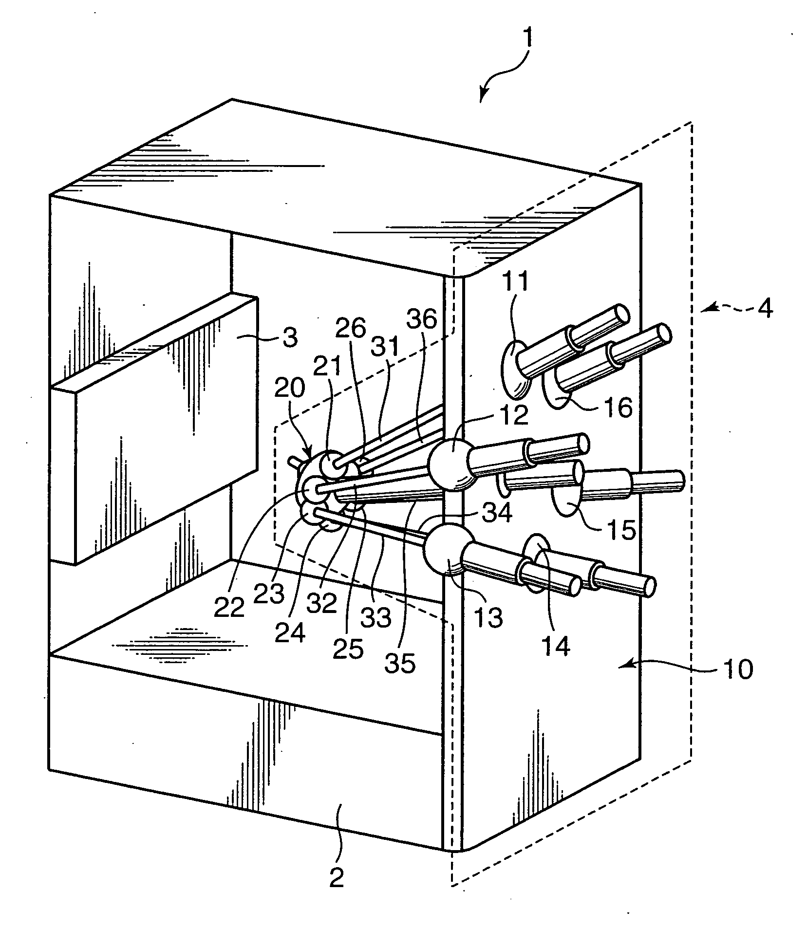
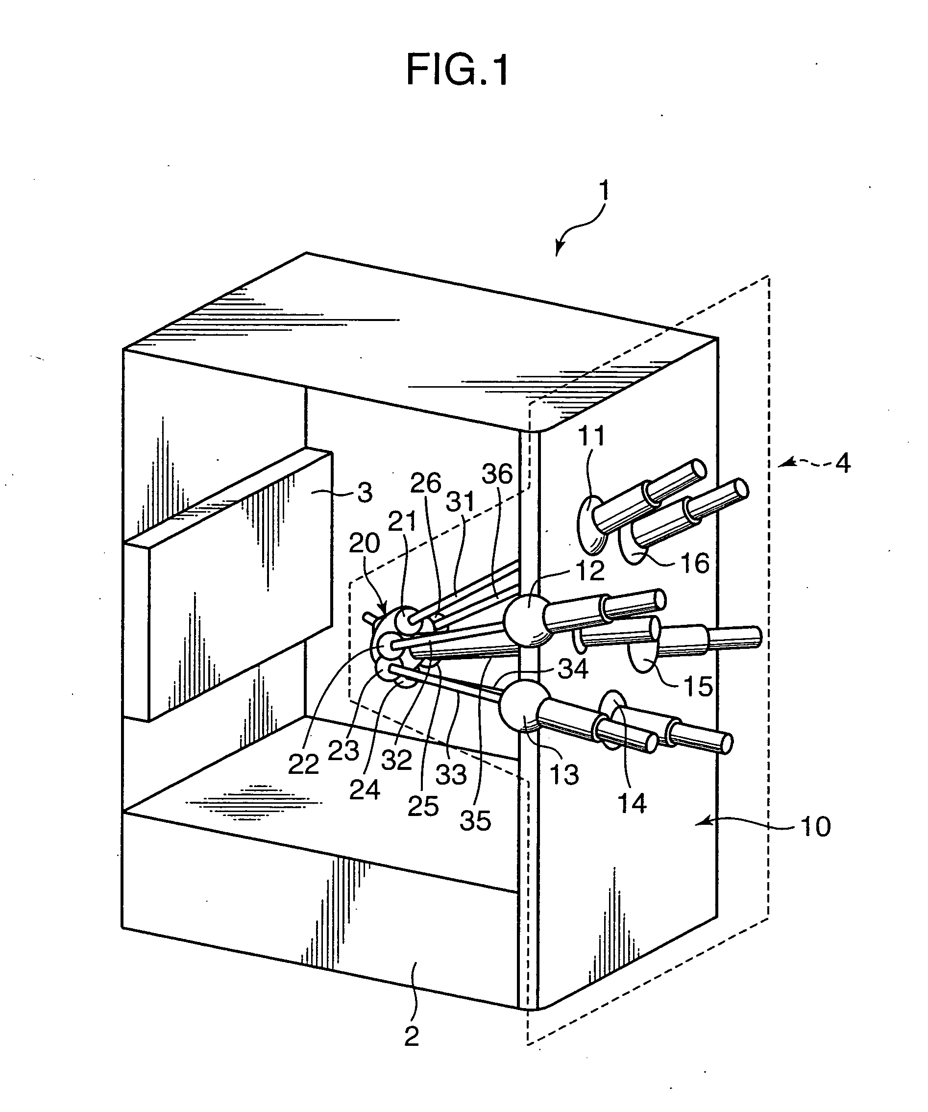
[0026] In the following, a preferred embodiment of the invention will be described with reference to the accompanying drawings. The embodiment will be described with reference to a 6×6 parallel kinematic machine, as an example of a parallel kinematic machine embodying the invention, which includes six joints on an end effecter and six joints on a base, more specifically, is in the form of the Stewart platform which has direct driving actuators, i.e., struts as driver shafts. It should be noted that, in the drawings, the elements or steps given with the same numerals or characters perform like operations, functions, and processings, and repeated description on the like operations, functions, and processings will be avoided herein.

[0027] Referring to FIG. 1, which is a perspective view showing a mechanical configuration of a parallel kinematic machine embodying the invention, the parallel kinematic machine 1 includes a base 10 supported by a support platform 2 and an end effecter 20....


PUM


Abstract

A parallel kinematic machine has a parallel kinematic mechanism including an end effecter and a parallel link mechanism. A numerical control device controls a position and orientation of the end effecter based on kinematics of the parallel kinematic mechanism. A posture setter sets an adjustment tool on the end effecter in a known posture in a reference coordinate system defined outside the parallel kinematic mechanism based on a measurement method. A data acquirer acquires data in accordance with a measurement method selecting code for designating the measurement method used by the posture setter in setting the adjustment tool in the known posture, and defines a correlation between kinematic parameters for the parallel kinematic mechanism and the reference coordinate system. A calculator calculates the kinematic parameters based on the acquired data by using a relational expression describing forward kinematics of the parallel kinematic mechanism.

Description

BACKGROUND OF THE INVENTION [0001] 1. Field of the Invention [0002] The present invention relates to a parallel kinematic machine, and a calibration technology of identifying kinematic parameters in the parallel kinematic machine. [0003] 2. Description of the Related Art [0004] A parallel kinematic mechanism which is provided with a base and an end effecter connected parallel to each other by plural driver shafts has higher rigidity and accuracy in posturing than a mechanism which is provided with a cantilever. The Stewart platform is a typical example of the parallel kinematic mechanisms. The Stewart platform has straight driver shafts or struts which are expanded or contracted to control the posture including a position and an orientation of an end effecter. For the highly accurate posturing, however, it is necessary to calculate accurate kinematic parameters such as the length of a strut, coordinates of a joint connecting a strut and a base, and a joint connecting a strut and the...

Claims


Application Information

Patent Timeline
IPC IPC(8): H01L27/00G05G11/00
CPCB25J9/1623B25J9/1692Y10T74/2036B25J9/0057B25J17/0266B25J9/00B25J11/00
Inventor NISHIBASHI, NOBUTAKAYAGI, KAZUAKI
Owner SHINNIPPON KOKI
Why Eureka
Try Eureka