Process for making necked nonwoven webs having improved cross-directional uniformity

Inactive Publication Date: 2007-06-21
KIMBERLY-CLARK WORLDWIDE INC
View PDF50 Cites 32 Cited by
  • Summary
  • Abstract
  • Description
  • Claims
  • Application Information

AI Technical Summary

Benefits of technology

[0009] The present invention is directed to a process for making a necked nonwoven web having improved cross-directional uniformity. The process includes the steps of providing a nonwoven web having an initial (first) width A in the cross-direction and reducing the width of the nonwoven web to a second width B without stretching the nonwoven web in the machine direction (i.e., prior to neck stretching the nonwoven web). This reduction in width is suitably accomplished by corrugating the nonwoven web in the cross direction.
[0010] Then, the corrugated nonwoven web is neck stretched in the machine direction to produce a necked nonwoven web having a third width C which is less than the first width A. The neck stretching is suitably accomplished by passing the corrugated nonwoven web through a first nip having a first surface velo

Problems solved by technology

This results in more extension of the web at the edges and

Method used


Image

  • Process for making necked nonwoven webs having improved cross-directional uniformity
  • Process for making necked nonwoven webs having improved cross-directional uniformity
  • Process for making necked nonwoven webs having improved cross-directional uniformity

Examples


Embodiment Construction

[0031] Referring to FIGS. 3A and 3B, a process for making a necked nonwoven material 22 includes the step of providing a nonwoven web 12 in an un-necked state, such as by unwinding it from a storage roll 10. The nonwoven web 12, which has a first width A, is passed through a corrugating station 50 (described further below). The station 50 corrugates the nonwoven web, and provides a corrugated nonwoven web 17 having a reduced width B which is less than the width A.

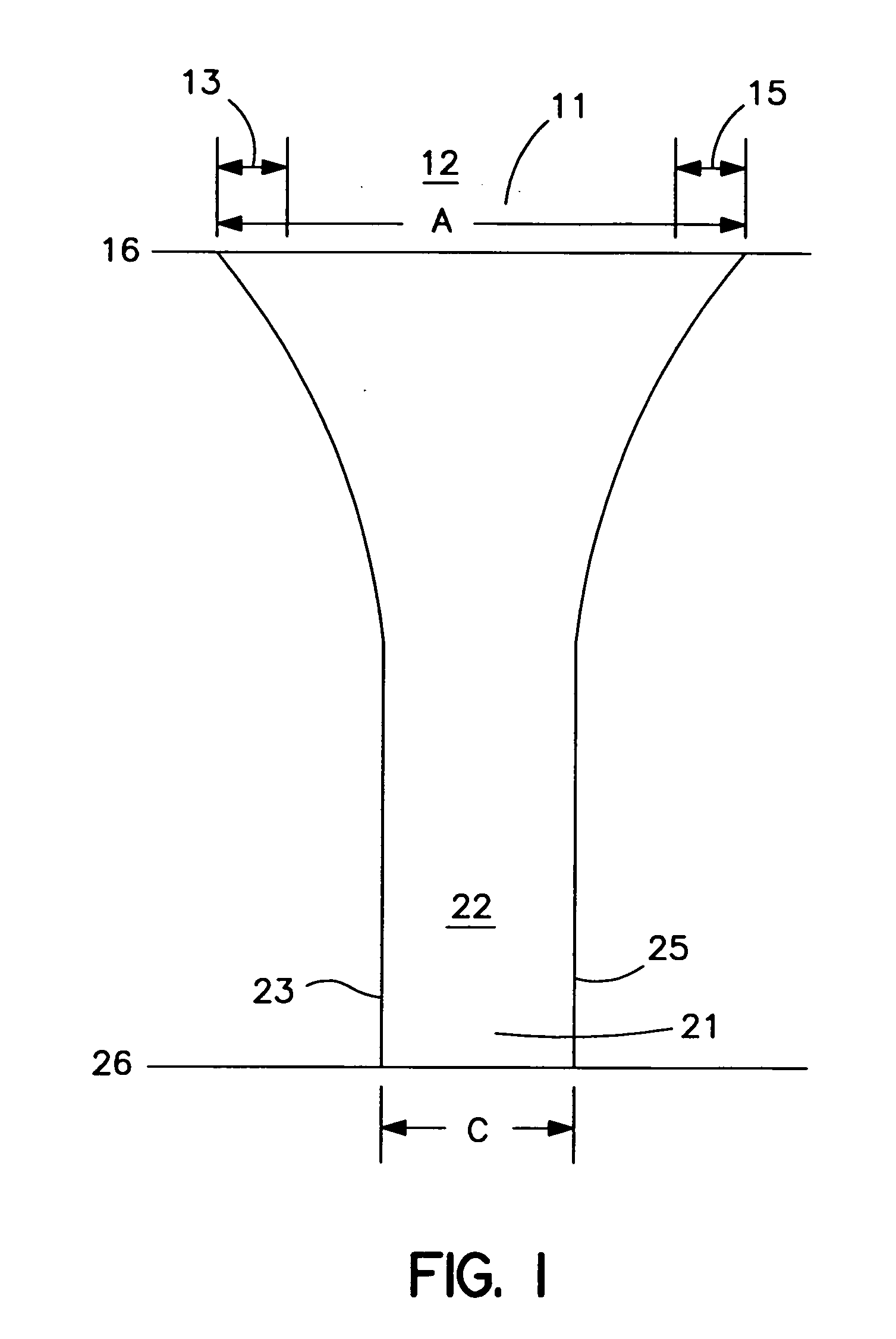
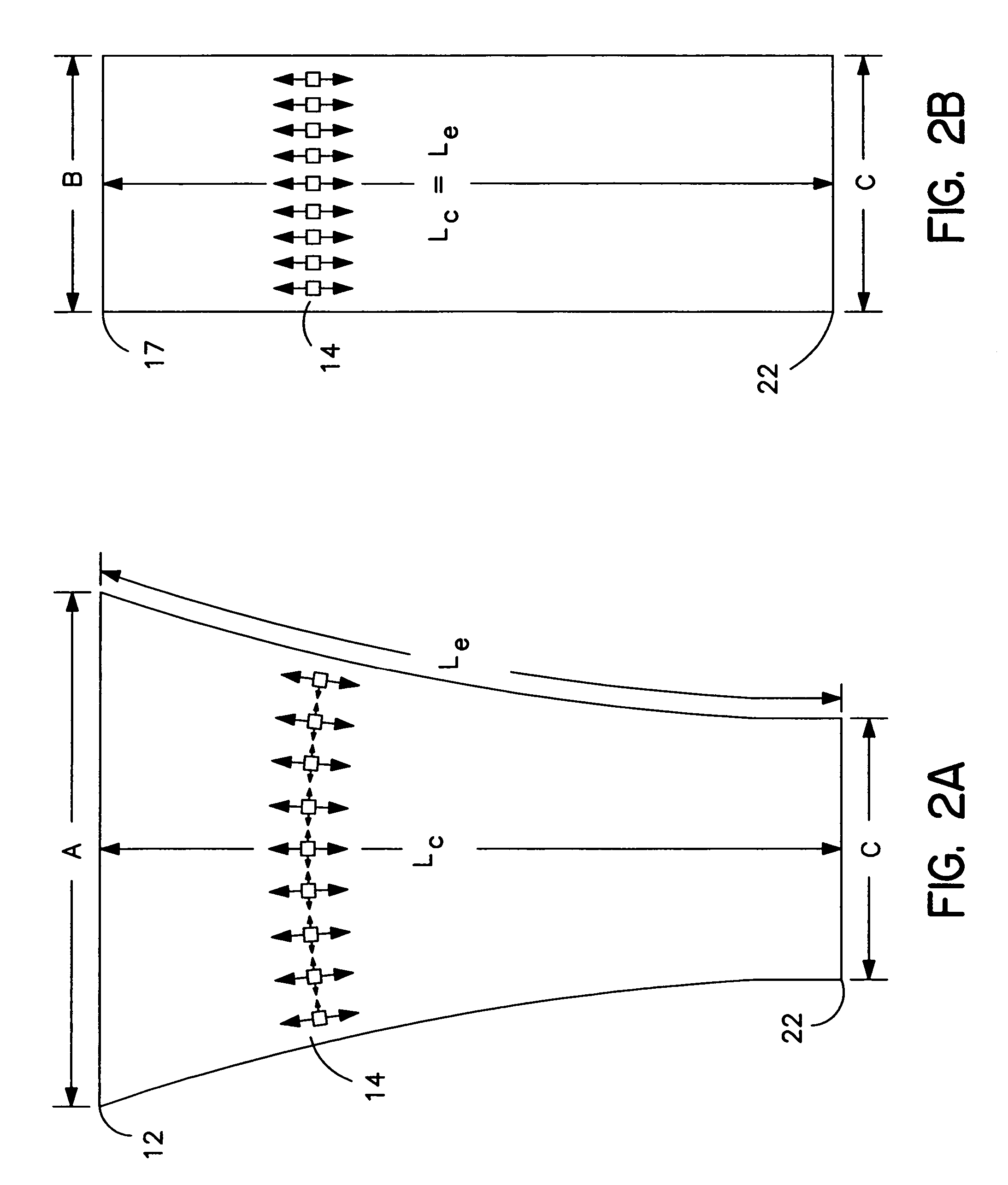
[0032] The desired reduced width B is best described with respect to the necked width C, which is the ultimate desired width of the necked nonwoven web. Referring to FIG. 2A, the prior art processes necked the nonwoven web from a starting width A, to provide a necked nonwoven web 22 having a necked width C. The necking was performed by stretching the nonwoven web in the machine direction to cause narrowing in the cross direction. The machine direction stretching in the center of the nonwoven web proceeded along a path Lc, ...


PUM

PropertyMeasurementUnit
Fractionaaaaaaaaaa
Fractionaaaaaaaaaa
Fractionaaaaaaaaaa

Abstract

Necked nonwoven webs having improved cross-directional uniformity are made by a process which includes the step (prior to neck stretching) of corrugating the nonwoven web to reduce its width from an initial width A to a reduced corrugated width B. The cross-directional uniformity is optimized as the corrugated width B approaches the ultimate width C of the necked nonwoven web.

Description

BACKGROUND OF THE INVENTION [0001] This invention is related to a process for making necked nonwoven webs and laminates having more uniform basis weights and stretching properties in the cross direction. [0002] Necked nonwoven webs, including necked spunbond webs, meltblown webs, combinations and the like, are often made using a process which is schematically illustrated in FIG. 1. A nonwoven web 12 having a starting width A is passed in its machine direction between a first nip 16, which can be a first pair of nip rollers traveling at a first surface velocity, and a second nip 26, which can be a second pair of nip rollers traveling at a second surface velocity which is faster than the first surface velocity. The surface velocity difference between the first and second nips results in formation of a narrower (“necked”) nonwoven web 22 having a necked width C which is less than the starting width A. [0003] The necked nonwoven web 22 generally includes fibers which are closer together...

Claims


Application Information

Patent Timeline
IPC IPC(8): B29C53/24B29C55/02
CPCA61F13/15707A61F13/4902B29C55/18B31F1/22B32B5/26B32B25/10B32B37/144B32B37/153B32B2038/0028B32B2305/20B32B2307/51D04H1/565D04H3/00D06C3/00B32B5/022B32B7/02B32B27/12B32B27/302B32B27/32B32B3/28B32B2262/0253B32B2274/00B32B2307/718D04H1/56
Inventor GERNDT, ROBERT J.HALL, DAVID W.
Owner KIMBERLY-CLARK WORLDWIDE INC
Why Eureka
Try Eureka