Speckle navigation system

Active Publication Date: 2007-06-21
CYPRESS SEMICON CORP
View PDF99 Cites 20 Cited by
  • Summary
  • Abstract
  • Description
  • Claims
  • Application Information

AI Technical Summary

Problems solved by technology

One problem with mechanical mice is that they are prone to inaccuracy and malfunction after sustained use due to dirt accumulation, and such.
In addition, the movement and resultant wear of the mechanical elements, particularly the shaft encoders, necessarily l

Method used


Image

  • Speckle navigation system
  • Speckle navigation system
  • Speckle navigation system

Examples


Embodiment Construction

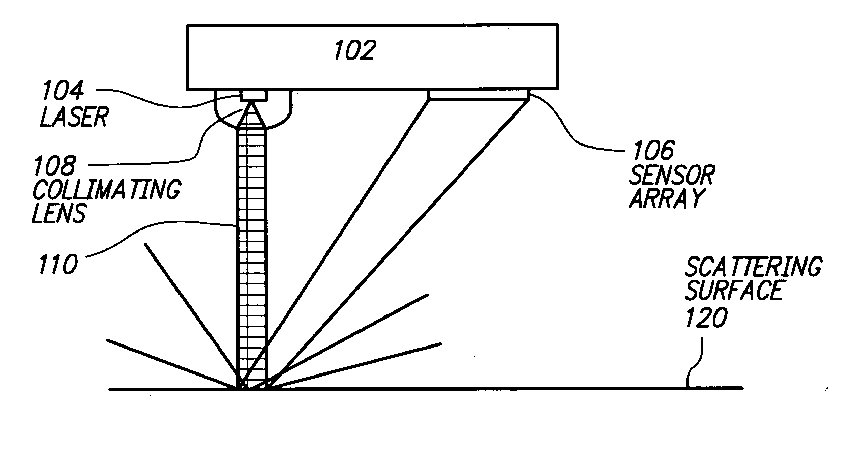
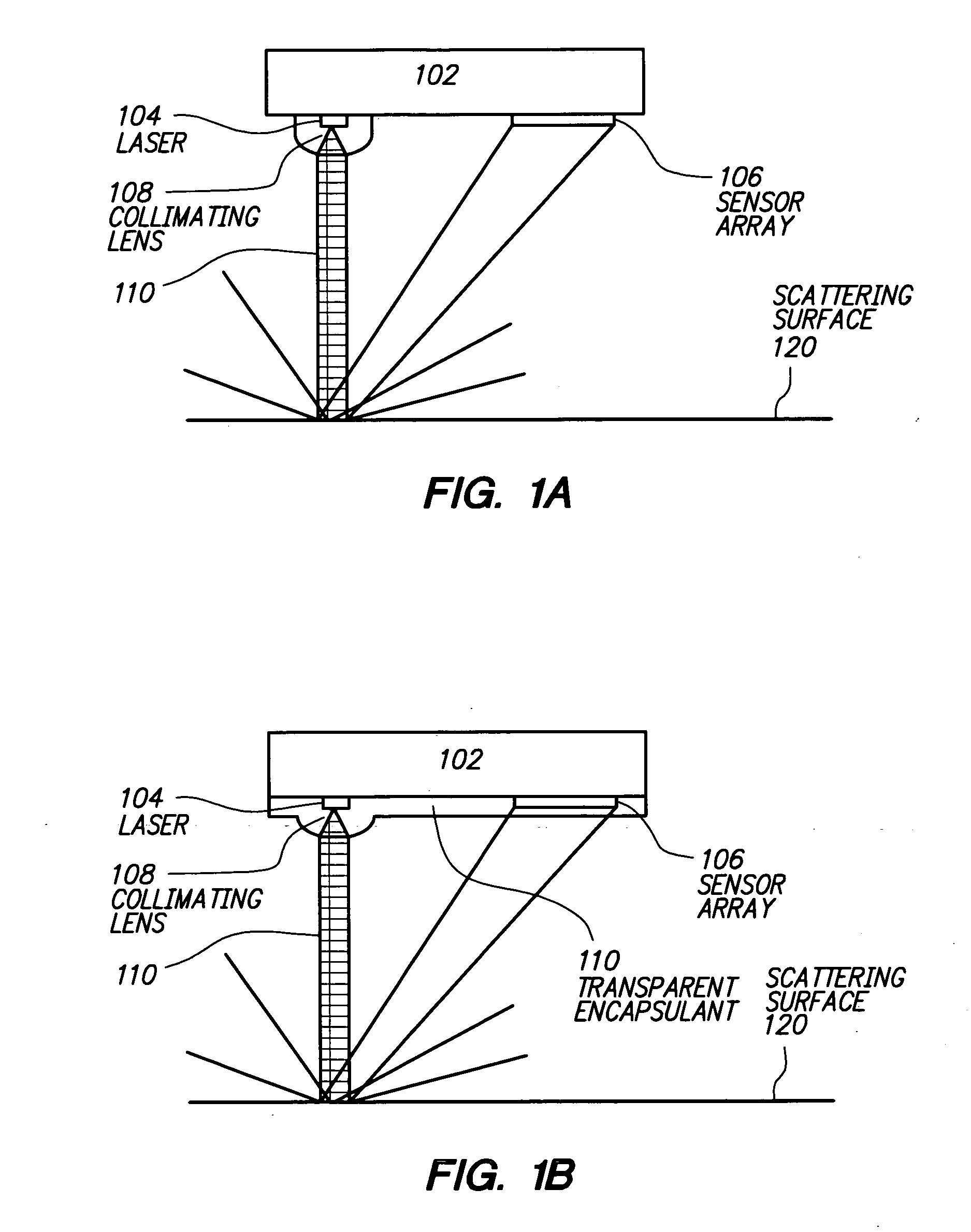
[0019]FIG. 1A is a cross-sectional diagram of a laser positioning device over a surface in accordance with an embodiment of the invention. As shown, the laser positioning device includes a planar substrate 102, a laser emitter 104, a sensor array 106, and a collimating lens 108. FIG. 1B shows a specific embodiment with a transparent encapsulant layer 110 that embodies the collimating lens 108. The encapsulant layer 110 also serves to protect the emitter 104 and the sensor array 106. In other embodiments, the collimating lens 108 may be plugged into a package covering the substrate 102, or may be part of a molded transparent plastic which covers the substrate 102, or may be implemented in other ways.

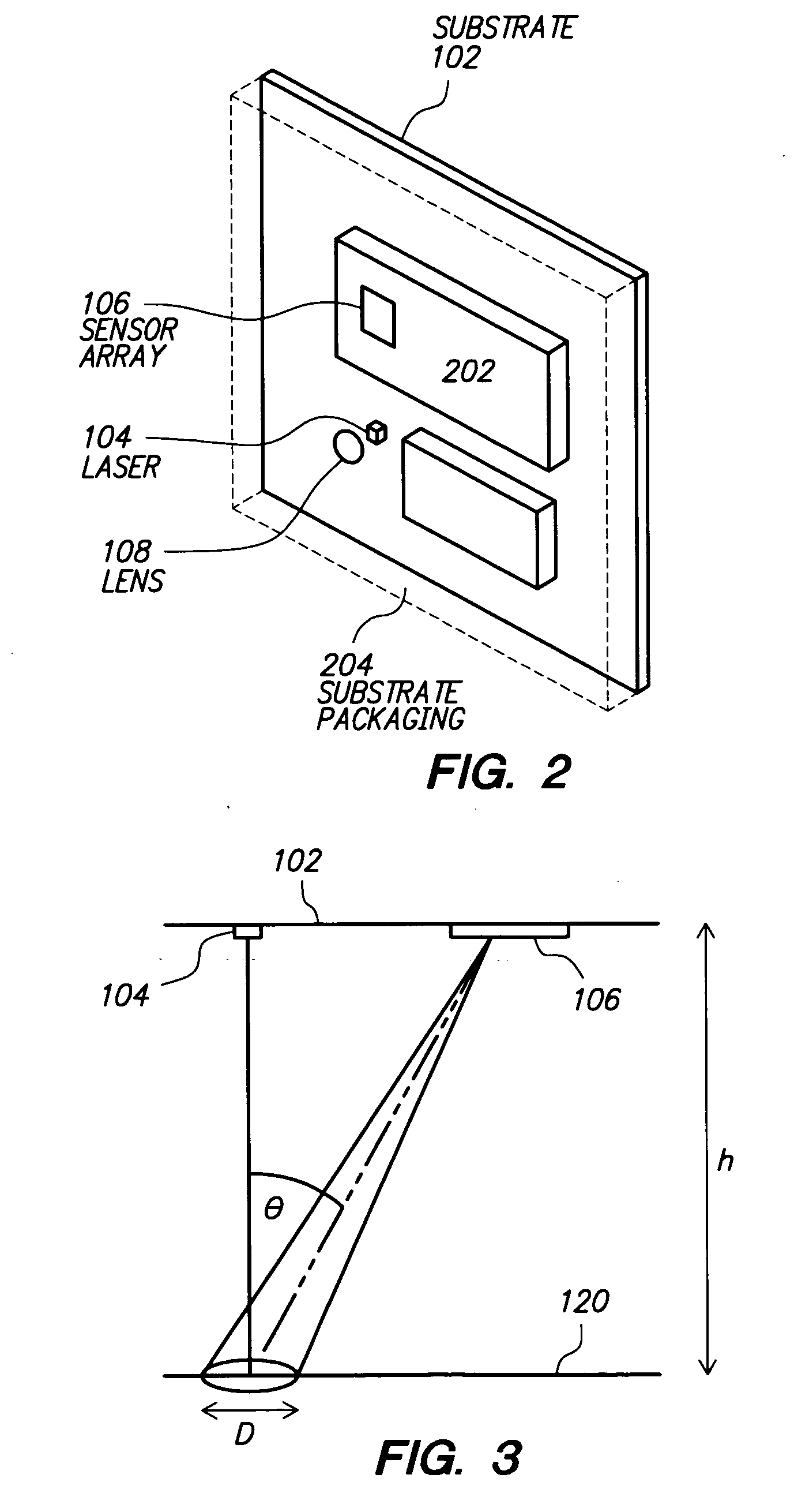
[0020] The laser positioning device may comprise, for example, a mouse device for user input into a computer system. The device may be constructed such that the planar substrate 102 is supported so as to lie parallel to the scattering surface 120 at a fixed distance. The device (and henc...


PUM


Abstract

One embodiment relates to a laser positioning device for sensing relative movement between a data input device and a surface by determining displacement of image features in a succession of images of the surface. The device forms a single integrated package, which includes a planar substrate and a transparent encapsulant that also embodies a collimating lens. Both a coherent light source and a sensor array and associated circuitry are configured on the planar substrate. Another embodiment relates to a method of sensing relative movement between a data input device and a surface. Coherent light is emitted from a laser and collimated so as to form a collimated illumination beam with a predetermined diameter, D, and a substantially uniform phase front. A speckle pattern is generated by impingement of the collimated illumination beam on the surface and detected by a sensor array. Other embodiments are also disclosed.

Description

TECHNICAL FIELD [0001] The present invention relates generally to an Optical Positioning Device (OPD), and methods of sensing movement using the same. BACKGROUND OF THE INVENTION [0002] Pointing devices, such as computer mice or trackballs, are utilized for inputting data into and interfacing with personal computers and workstations. Such devices allow rapid relocation of a cursor on a monitor, and are useful in many text, database and graphical programs. A user controls the cursor, for example, by moving the mouse over a surface to move the cursor in a direction and over distance proportional to the movement of the mouse. Alternatively, movement of the hand over a stationary device may be used for the same purpose. [0003] Computer mice come in both optical and mechanical versions. Mechanical mice typically use a rotating ball to detect motion, and a pair of shaft encoders in contact with the ball to produce a digital signal used by the computer to move the cursor. One problem with ...

Claims


Application Information

Patent Timeline
IPC IPC(8): G09G5/08
CPCG06F3/0317G06F3/03G06F3/0354G09G5/08
Inventor SPURLOCK, BRETT A.TRISNADI, JAHJA I.SANDERS, STEVENCARLISLE, CLINTON B.
Owner CYPRESS SEMICON CORP
Why Eureka
Try Eureka