Projection display, projection optical system and transmission lens or free curved lens

a projection optical system and projection display technology, applied in the field of projection displays, can solve the problems of inability to cope with aberration, increase distortion, and increase distortion, so as to achieve the effect of increasing distortion and aberration, and preparing for coping

Active Publication Date: 2007-06-21
MAXELL HLDG LTD
View PDF47 Cites 10 Cited by
  • Summary
  • Abstract
  • Description
  • Claims
  • Application Information

AI Technical Summary

Benefits of technology

[0007] It is an object of the present invention to provide a technique capable of displaying an image insignificantly subject to trapezoidal distortion and aberration, of

Problems solved by technology

When an image is projected on a screen in an oblique projection mode at a predetermined angle to a normal to a major surface of the screen, for example, from a level below that of the screen, the image projected on the screen is subject to trapezoidal distortion and to optical aberration due to the difference in projection distance between light beams projected on an upper part of the screen and those projected on a lower part of the screen.
When the aberration is corrected by such a method, an image displayed on the screen is likely to be longitudinally displaced.
Any measures are not taken to cope with aberration and increase in distortion due to the deformatio

Method used


Image

  • Projection display, projection optical system and transmission lens or free curved lens
  • Projection display, projection optical system and transmission lens or free curved lens
  • Projection display, projection optical system and transmission lens or free curved lens

Examples


Embodiment Construction

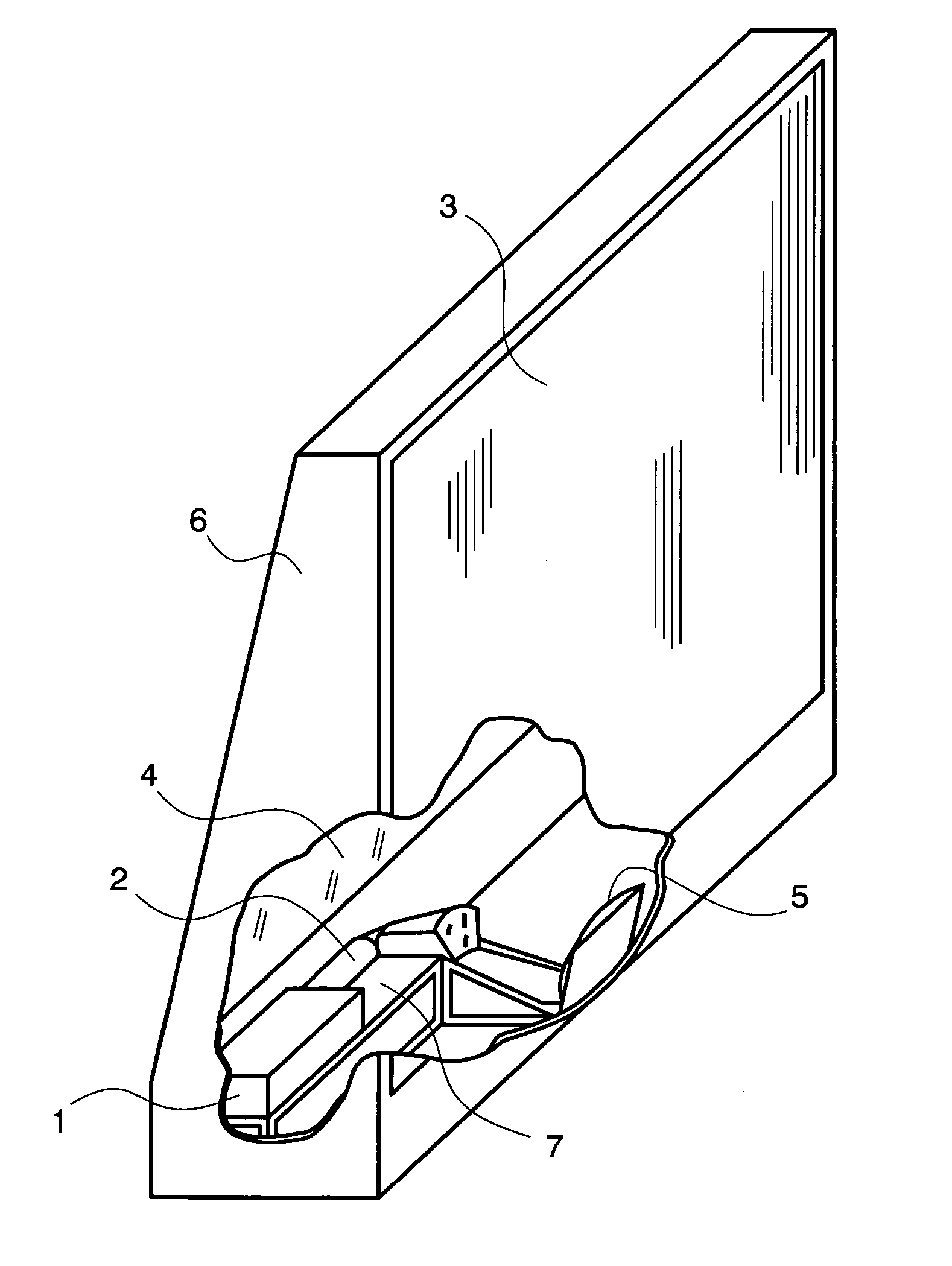
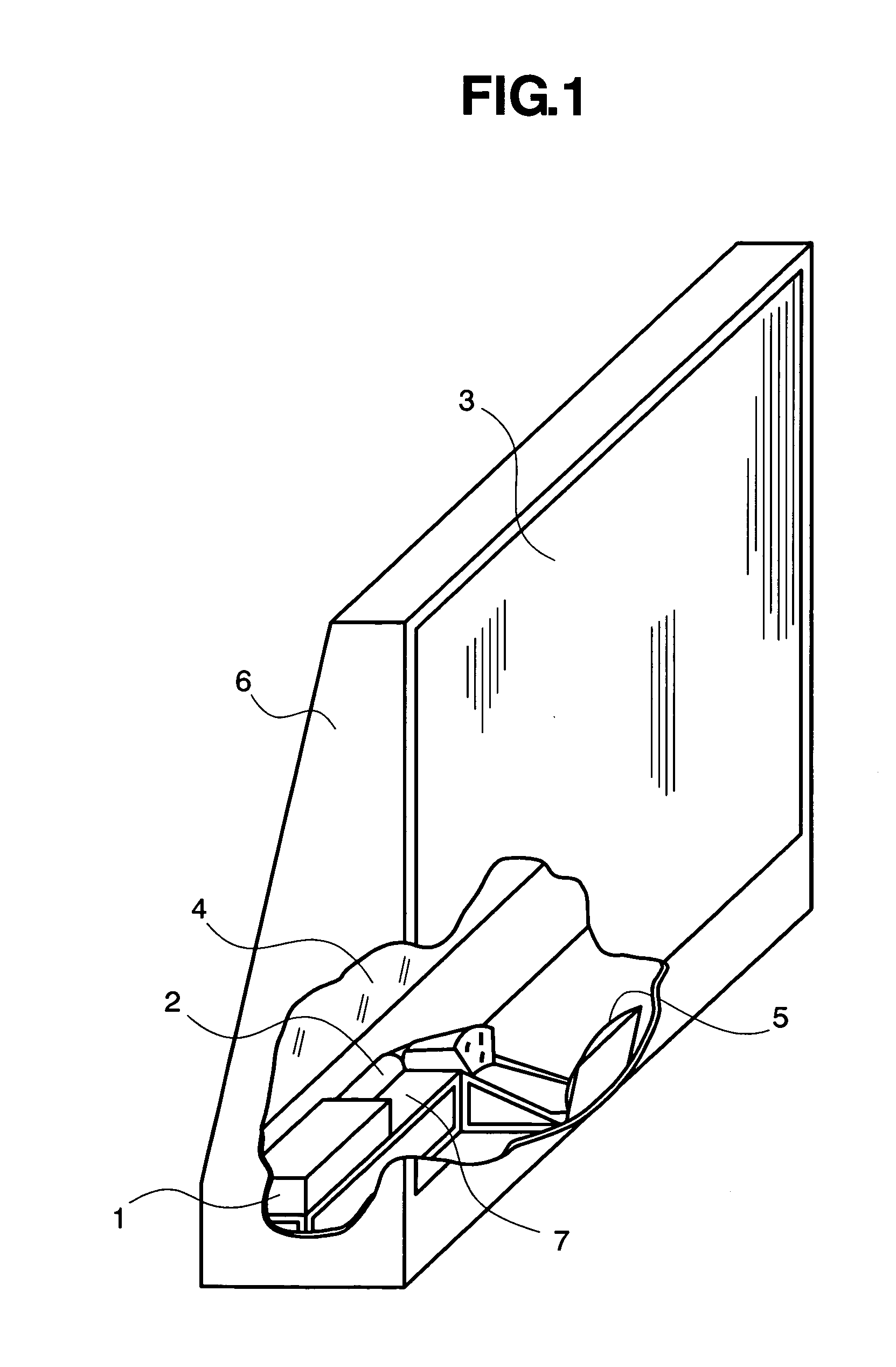
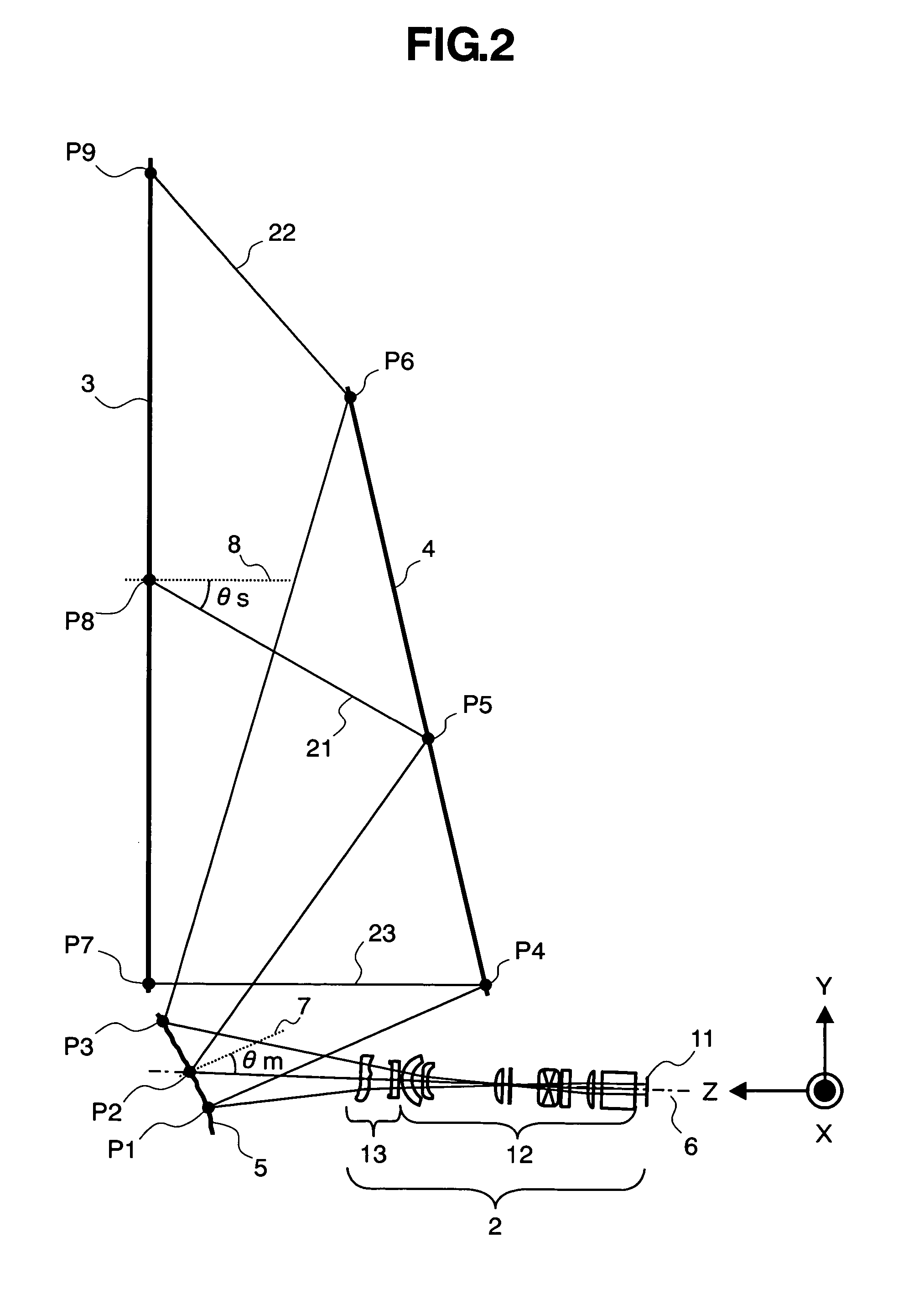
[0030] Preferred embodiments of the present invention will be described with reference to the accompanying drawings. Referring to FIG. 1 showing a projection display in a preferred embodiment according to the present invention in a partly cutaway perspective view, an image generator 1 displays a small image. The image generator 1 is an optical modulator, such as a reflection or transmission liquid crystal panel or a display device provided with a plurality of micromirrors. The image generator 1 may be a projection CRT. An image generated by the image generator 1 is projected through a projection lens 2 included in a first optical system on a screen 3. A flat reflecting mirror 4 is disposed in an optical path between the projection lens 2 and the screen 3 to form the projection display in a small depth. A free curved mirror 5, which is a component of a second optical system, is interposed between the projection lens 2 and the flat reflecting mirror 4. Light traveled through the proje...


PUM


Abstract

A projection display is capable of suppressing both the trapezoidal distortion of an enlarged image projected on a screen by oblique projection and aberrations resulting from oblique projection and includes a projection optical system provided with lenses that can be easily manufactured and assembled. The projection optical system for obliquely projecting an image formed by a display device on the screen includes a free curved lens having a rotationally asymmetric free curved surface. The free curved lens has fringing parts having outlines of a shape coinciding with an arc of a circle having the center on the optical axis of the free curved lens.

Description

BACKGROUND OF THE INVENTION [0001] The present invention relates to a projection display capable of projecting a color image to display an enlarged color picture. [0002] A projection display for displaying an enlarged image of an image formed by a display device using reflection or transmission liquid crystal panel or micromirrors is required to form a sufficiently enlarged image on a screen and to have a small depth. A projection optical unit and a projection display intended to meet such requirements are disclosed in JP-A 2001-264627. The known projection optical unit and the known projection display project an enlarged image obliquely on a screen. Such an image projection mode will be referred to as “oblique image projection mode”. A method of optical adjustment of a projection display employing a curved mirror for oblique projection is disclosed in, for example, JP-A 2002-350774. [0003] When an image is projected on a screen in an oblique projection mode at a predetermined angle...

Claims


Application Information

Patent Timeline
IPC IPC(8): G03B21/22
CPCG02B3/02G02B13/16G02B13/18G02B27/0025G03B21/10G03B21/14G03B21/28G03B21/147
Inventor HISADA, TAKANORIYOSHIKAWA, HIROKIOHISHI, TETSUHIRATA, KOJIOGURA, NAOYUKI
Owner MAXELL HLDG LTD
Why Eureka
Try Eureka