
Portable electronic device comprising a folded substrate

a technology of electronic devices and folded substrates, applied in the direction of hearing aid housing, electrical apparatus construction details, mounting/interconnection of hearing aids, etc., can solve the problem of scarce space in a hearing aid

Active Publication Date: 2011-12-08
OTICON
View PDF5 Cites 53 Cited by
  • Summary
  • Abstract
  • Description
  • Claims
  • Application Information

AI Technical Summary

Benefits of technology

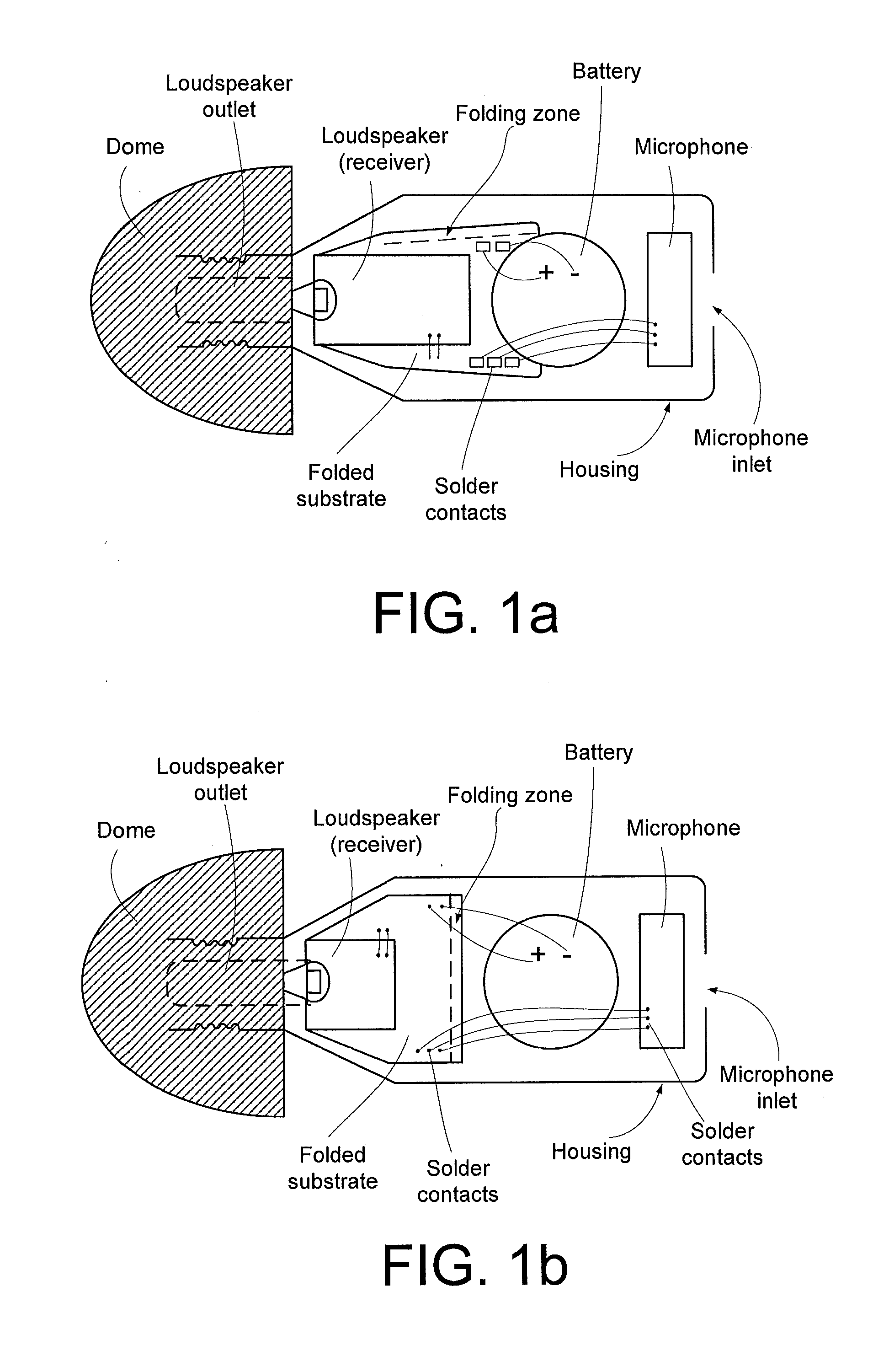
[0016]This has the advantage of providing a larger area on the substrate to place components and soldering points thereby improving the use of the available space in the portable electronic device.
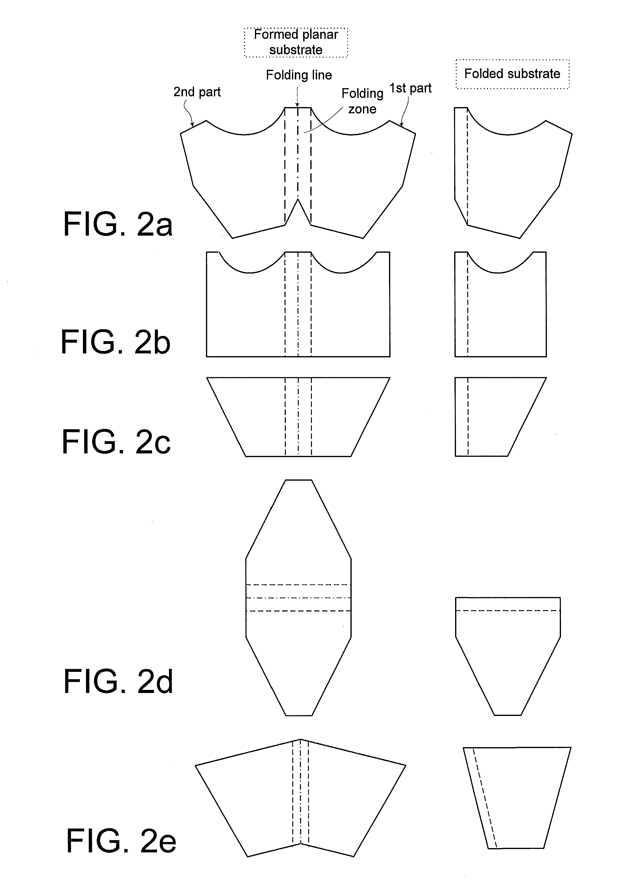
[0027]In an embodiment, the planar substrate is adapted to have a certain general critical folding radius and a smaller critical folding radius in a folding zone around said folding line. The critical folding radius of a planar substrate is in the present context taken to mean the smallest radius by which the substrate can be folded to provide a folded substrate folded 180° along a folding line without damaging the functional structures (e.g. printed conductors) on the surface of or embedded in the planar substrate.
[0028]In an embodiment, the planar substrate has a certain general thickness and a smaller thickness in a folding zone around said folding line to provide a decreased critical folding radius of the substrate in said folding zone compared to a critical folding radius for the substrate in general.
[0032]In an embodiment, the folded substrate comprises one or more distance keeping components adapted for ensuring a minimum distance between opposing surfaces of the folded substrate. In an embodiment, a distance keeping component comprises a locking mechanism for locking two ends of a finalized folded substrate. This has the advantage of easing handling of the folded substrate during manufacturing of the device. In an embodiment, a distance keeping component is located in a part of the substrate where no other components are easily mounted (e.g. in a wedge formed part of the substrate).
[0033]In an embodiment, the planar substrate—e.g. a printed circuit board (PCB) (e.g. a flexible PCB)—is adapted to provide that electronic components can be mounted directly onto one or both sides of the planar substrate using a Surface Mount Technology (SMT) (as opposed to mounting technologies e.g. involving pins extending through holes in the planar substrate). Components that are specifically adapted for being surface mounted are typically physically smaller than corresponding components with pins. The use of surface mount components is in general an advantage where relatively small dimensions and a relatively high degree of automation in the mounting process is an advantage. Electronic components adapted for being surface mount are often referred to as SMD (Surface Mount Device) components. An SMD component has electrical terminals in the form of metalized areas (e.g. in the form of end caps) suitable for being soldered (typically by a machine) directly onto solderable electrically conducting pads on the surface of a substrate provided with solder paste for receiving a particular SMD component (the planar substrate, e.g. a PCB, typically having predefined electrically conducting patterns for interconnecting the various SMD components (and possible other electronic components) on the substrate and possibly for connecting the circuitry to external parts).
[0062]This has the advantage of providing a multitude of folded substrates (including mounted components) in a batch type (fully or partially automated) process.

Problems solved by technology

Space is a scarce resource in a hearing aid.

Method used


Image

  • Portable electronic device comprising a folded substrate
  • Portable electronic device comprising a folded substrate
  • Portable electronic device comprising a folded substrate

Examples


Embodiment Construction

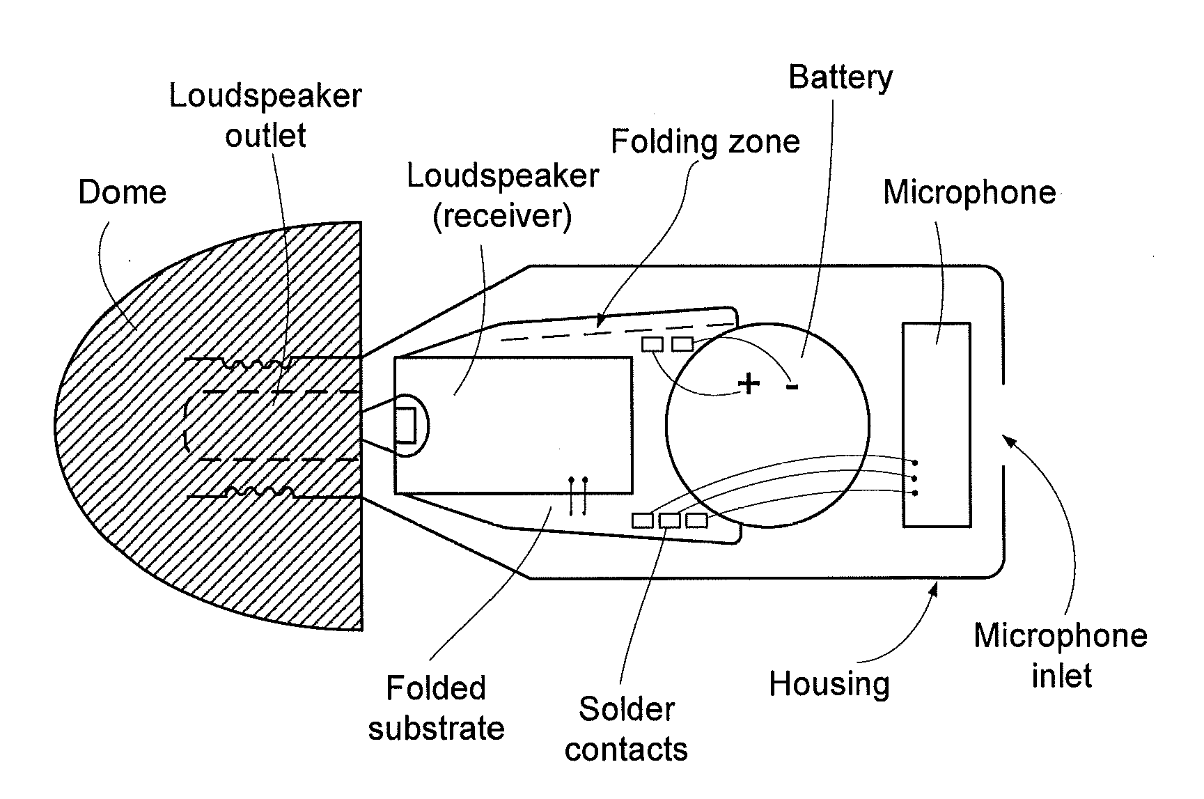
[0011]An aspect of the idea is to shape a flexible substrate carrying at least some of the electronic components of the portable electronic device to fit the battery form (and / or to the form of another relatively large component located external to the substrate and / or to the inner contour or shape of the housing) in a three dimensional structure.

[0012]An object of the present application is to facilitate miniaturization of a portable electronic device, such as a hearing aid.

[0013]Objects of the application are achieved by the invention described in the accompanying claims and as described in the following.

[0014]A Portable Electronic Device:

[0015]An object of the application is achieved by a portable electronic device comprising a) a folded substrate carrying components of the device, and b) another, separate component having a fixed outer contour, and c) a housing for enclosing said folded substrate and said separate component, said housing having an inner contour, wherein said fol...


PUM

PropertyMeasurementUnit
angleaaaaaaaaaa
folding angleaaaaaaaaaa

Abstract

A portable electronic device having a) a folded substrate carrying components of the device, and b) another, separate component having a fixed outer contour, and c) a housing for enclosing said folded substrate and said separate component, said housing having an inner contour, wherein said folded substrate is folded from a planar substrate along a folding line, said folded substrate exhibiting outer edges comprising a folded edge following said folding line. A method of manufacturing a folded substrate. An object of the present application is to facilitate miniaturization of a portable electronic device, such as a hearing aid. A problem is solved in that the folded substrate is shaped to provide that at least one of said outer edges follow(s) the fixed outer contour of the separate component and / or the inner contour of said housing.

Description

CROSS REFERENCE TO RELATED APPLICATIONS[0001]The present application claims the benefit of European Application No. 10165072.9, filed on Jun. 7, 2010 and claims the benefit of U.S. Provisional Application No. 61 / 351,949. The entire contents of each of European Application No. 10165072.9 and U.S. Provisional Application No. 61 / 351,949 are hereby incorporated herein by reference.TECHNICAL FIELD[0002]The present application relates to portable electronic devices, e.g. hearing aids, e.g. such hearing aids that are adapted to be located in the ear canal of a user. The disclosure relates specifically to a portable electronic device comprising a) a folded substrate carrying components of the device, and b) another, separate component having a fixed outer contour, and c) a housing for enclosing said folded substrate and said separate component, said housing having an inner contour, wherein said folded substrate is folded from a planar substrate along a folding line, said folded substrate ex...

Claims


Application Information

Patent Timeline
Patent Type & Authority Applications(United States)
IPC IPC(8): H04R25/00H05K3/30H05K7/00
CPCH04R25/60H04R25/658Y10T29/4913H05K1/189H04R2225/023H04R25/00H04R25/602H04R2225/025H04R25/609H04R25/65
Inventor MOLLER, KENNETH RUESKOVLARSEN, JAN T.L.
Owner OTICON
Learn More