
Movable part locking jig and image forming apparatus incorporating such movable part locking jig

a technology of locking jig and moving parts, which is applied in the direction of digitally marking record carriers, instruments, optics, etc., can solve the problems of erroneous reading of recorded radiation image information, vibrations that are inevitably applied to the mobile image information reading apparatus, and subject to unexpected shocks, etc., and achieves the effect of simple arrangemen

Inactive Publication Date: 2007-06-21
FUJIFILM CORP
View PDF4 Cites 4 Cited by
  • Summary
  • Abstract
  • Description
  • Claims
  • Application Information

AI Technical Summary

Benefits of technology

[0014] It is a general object of the present invention to provide a movable part locking jig which is capable of locking a movable part of an image forming apparatus with a simple arrangement without enlarging and weighing jig configuration, and an image forming apparatus incorporating such a movable part locking jig therein.
[0015] A major object of the present invention is to provide a movable part locking jig which allows a portable image forming apparatus to be moved reliably without being subjected to vibrations, and an image forming apparatus incorporating such a movable part locking jig therein.
[0016] Another object of the present invention is to provide a movable part locking jig which allows a locking jig to be used as a jig for locking a movable part of an image forming apparatus and also to be effectively used as a working table, and an image forming apparatus incorporating such a movable part locking jig therein.
[0017] According to the present invention, a movable part locking jig (a supply unit locking jig or an image processor locking jig), instead of an image recording medium, is loaded into a loader in an image forming apparatus, for locking movable parts in the image forming apparatus with a simple arrangement. Since the movable parts are securely locked in position in the image forming apparatus, the image forming apparatus can be moved reliably without trouble. The image forming apparatus, though it has precise mechanisms therein, can be small in size, light in weight, and handled with ease in hospitals or the like.

Problems solved by technology

When a mobile image information reading apparatus is moved around in a hospital, some vibrations are inevitably applied to the mobile image information reading apparatus.
Since the mobile image information reading apparatus is handled in different places, it may be subject to unexpected shocks in certain locations.
If the mobile image information reading apparatus, which is a precision apparatus, undergoes vibrations or shocks, it tends to have mechanical trouble such as loose screws or the like, which may lead to erroneous reading of recorded radiation image information.
Such a reading error greatly affects the image quality of the radiation image information.
If the applied vibrations or shocks are extremely intensive, then the mobile image information reading apparatus itself fails to operate.
As a result, the availability factor of the mobile image information reading apparatus is lowered to the extent that the convenience of the mobile image information reading apparatus is lost, losing its convenience.
However, since the clutch brake is disposed in the image information reading apparatus, the image information reading apparatus is heavy in weight and large in size.
Therefore, it is difficult for the disclosed image information reading apparatus to satisfy requirements for small, lightweight mobile image information reading apparatus.
In addition, as the reading head is not locked itself, it is not completely free of vibrations and shocks.
The same problems also arise in image information recording apparatus (image forming apparatus) in which an image recording medium such as an X-ray photographic film is supplied to a recording unit and radiation image information is recorded in the image recording medium by the recording unit.

Method used


Image

  • Movable part locking jig and image forming apparatus incorporating such movable part locking jig
  • Movable part locking jig and image forming apparatus incorporating such movable part locking jig
  • Movable part locking jig and image forming apparatus incorporating such movable part locking jig

Examples


Embodiment Construction

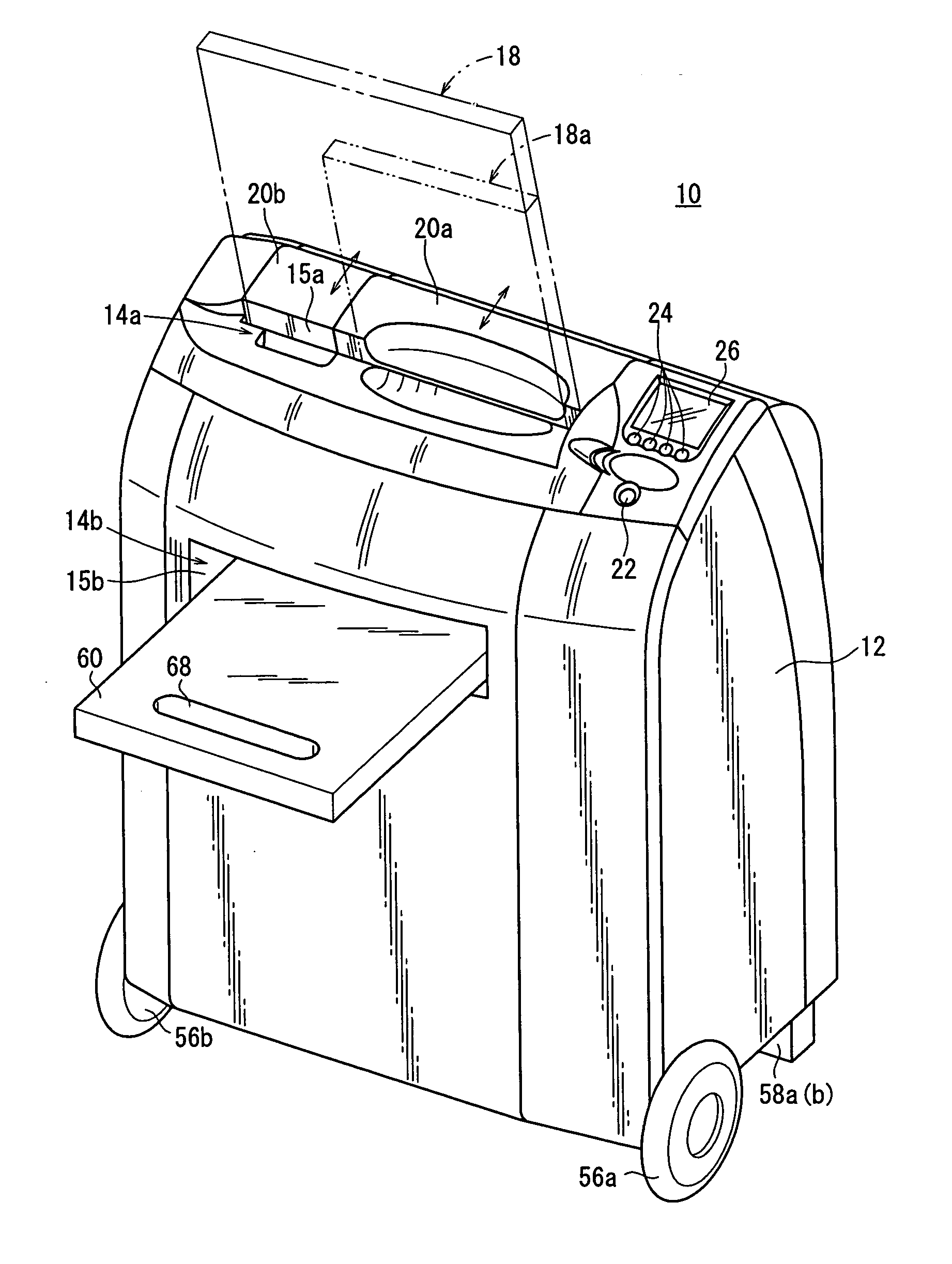
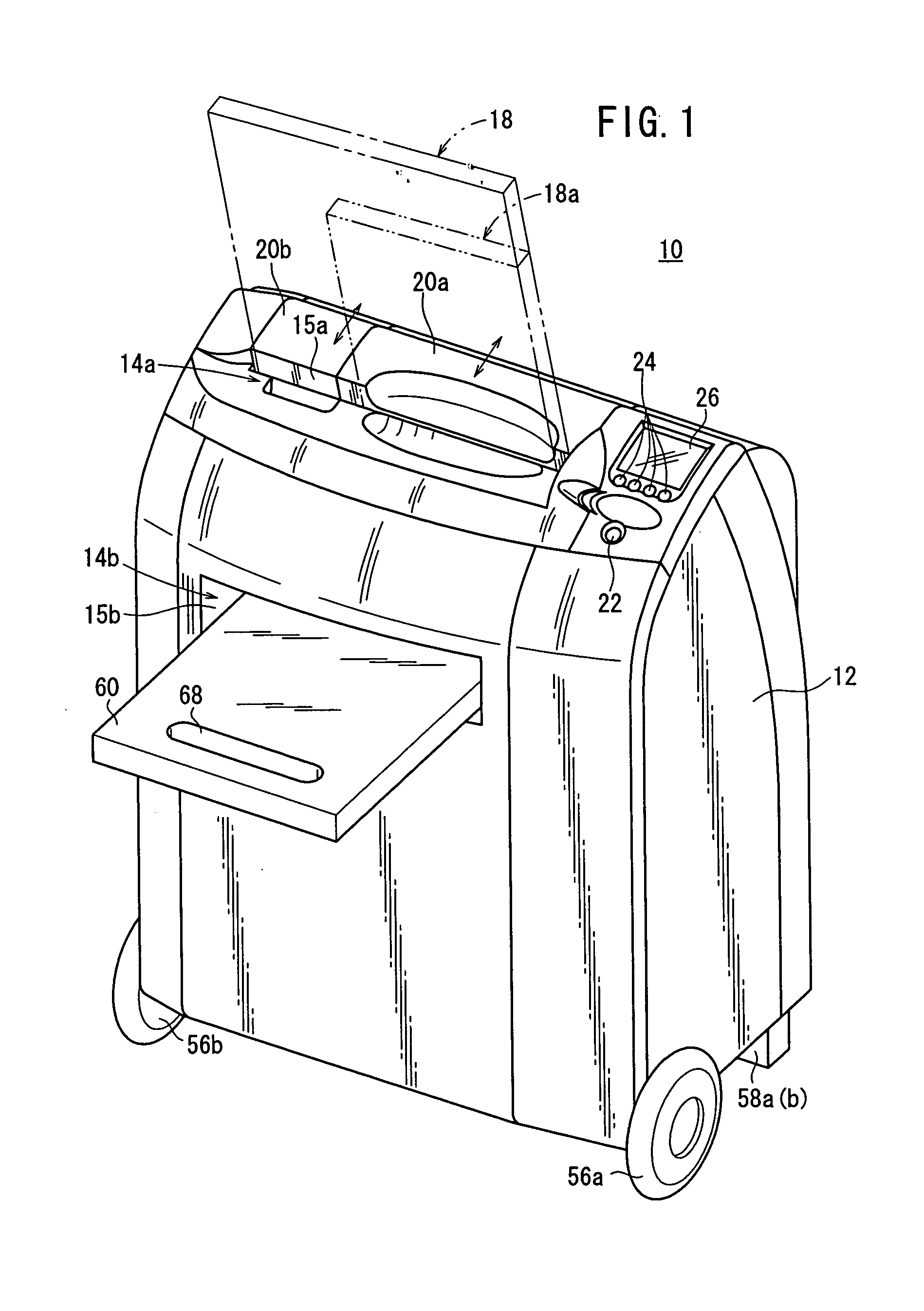
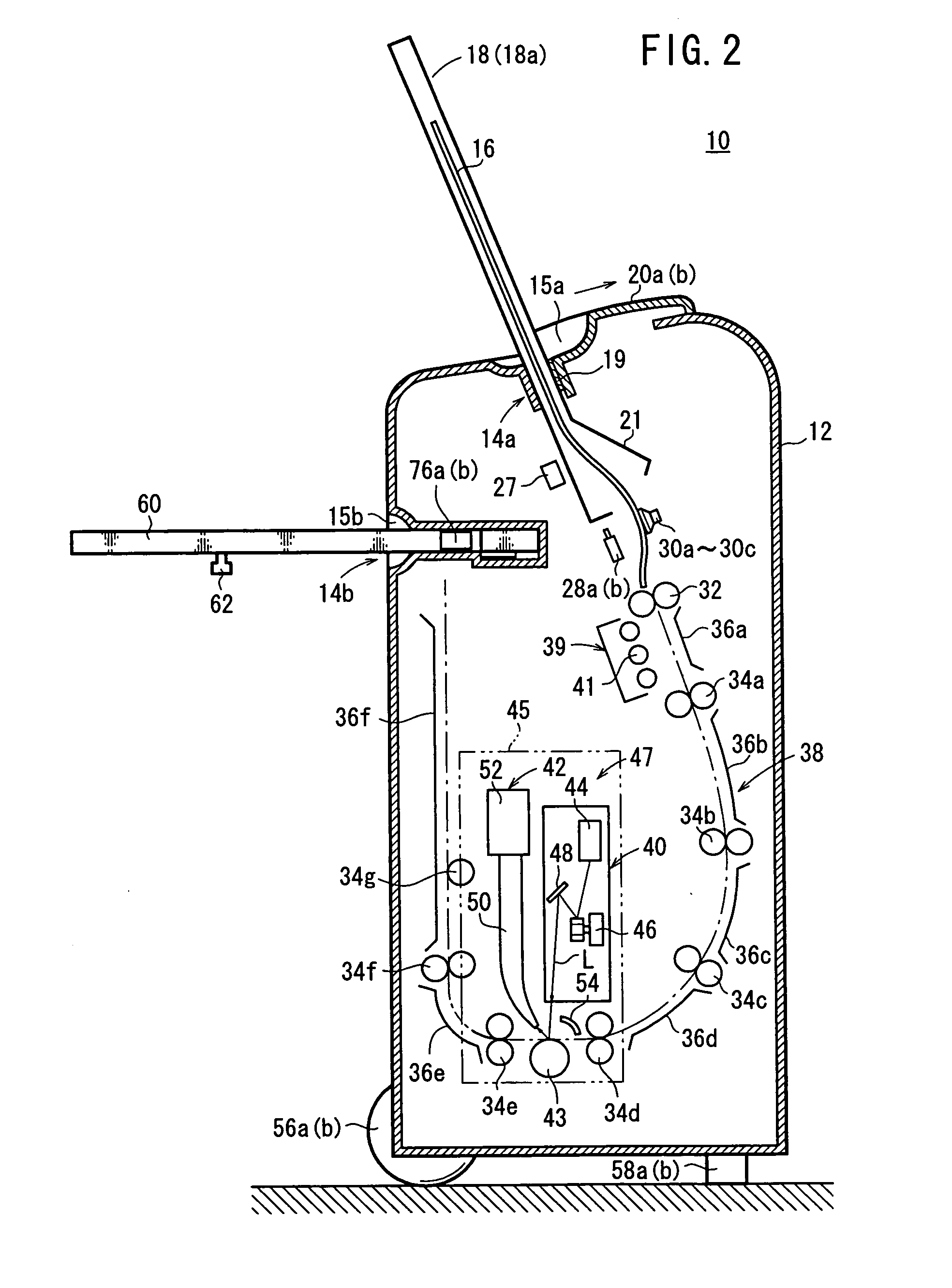
[0032]FIG. 1 shows in perspective a radiation image forming apparatus 10 according to an embodiment of the present invention, and FIG. 2 shows in vertical cross section internal structural details of the radiation image forming apparatus 10.

[0033] As shown in FIG. 1, the radiation image forming apparatus 10 has a casing 12 with a cassette loader 14a disposed in an upper wall thereof. The cassette loader 14a has a loading slot 15a into which either a cassette 18 or a cassette 18a housing a stimulable phosphor panel 16 (hereinafter also referred to as “IP”) with radiation image information recorded therein is loaded. The cassette 18a is smaller in size than the cassette 18.

[0034] The cassette loader 14a has covers 20a, 20b individually displaceable in the directions indicated by the respective allows. When the larger-size cassette 18 is to be loaded, both the covers 20a, 20b are displaced to open the loading slot 15a in its entirety to allow the larger-size cassette 18 to be inserte...


PUM


Abstract

A movable part locking jig is loaded into a cassette loader in a radiation image forming apparatus, and a lever is moved to project casing locking members from opposite side walls of a casing, thereby locking the movable part locking jig in the radiation image forming apparatus. Movable part locking members also projects to be brought into abutment against suction cups disposed near the cassette loader, thereby locking the suction cups. Then, the radiation image forming apparatus is moved to a desired location.

Description

BACKGROUND OF THE INVENTION [0001] 1. Field of the Invention [0002] The present invention relates to a movable part locking jig and a portable image forming apparatus incorporating such a movable part locking jig therein. [0003] 2. Description of the Related Art [0004] There has been known in the art an X-ray photographic film for use as an image recording medium for recording radiation image information of a subject such as a human being. There has also been widely used a stimulable phosphor panel instead of the X-ray photographic film. The stimulable phosphor panel has a stimulable phosphor layer which, when exposed to an applied radiation (X-rays, α-rays, β-rays, γ-rays, electron beams, ultraviolet radiation, or the like), stores part of the energy of the radiation, and, when subsequently exposed to stimulating rays such as laser beam or visible light, emits stimulated light in proportion to the stored energy of the radiation. [0005] These image recording mediums are usually hand...

Claims


Application Information

Patent Timeline
IPC IPC(8): H04N1/04
CPCG03B42/04H04N1/00567H04N1/00602H04N1/00607H04N1/0062H04N1/1135H04N1/121H04N2201/0412H04N2201/0444
Inventor OHTA, YASUNORIMATSUOKA, YOSHIAKI
Owner FUJIFILM CORP
Learn More