
Polarizing glass

a technology of polarizing glass and glass, applied in the field of polarizing glass, can solve the problems of high reliability of polarizing glass, limited use, and barely used, and achieve the effect of favorable polarizing characteristics

Inactive Publication Date: 2007-06-21
ARISAWA MFG CO LTD
View PDF1 Cites 5 Cited by
  • Summary
  • Abstract
  • Description
  • Claims
  • Application Information

AI Technical Summary

Benefits of technology

[0011] In order to solve the above-mentioned problem, according to a first aspect of the invention, there is provided a polarizing glass which includes a base glass exhibiting dichroism and formed of a transparent glass whose absorption edge of incident light is equal to or less than 350 nm when wavelength is converted into a variable, and metal having anisotropic shape dispersed and oriented within said base glass, a real number part of dielectric constant of said metal being minus or crosses over 0 with energy higher than 3.5 eV when the energy is converted into a variable, and reflectivity of said metal being equal to or higher than 80% in the visible light region. It enables the polarizing glass to have the favorable polarizing characteristics in the visible light region.

Problems solved by technology

However, although the polarizing glass has such high reliability, its use is limited almost to the near infrared region that is the wavelength region of optical communications and it is barely used in the visible light region such as the field of liquid crystal.
It is because the polarizing glass has had the following problems in using in the visible light region.
Therefore, although the polarizing glass in which the elliptic silver particles are dispersed and oriented exhibits favorable polarizing characteristics in the specific wavelength region of the visible light region, the polarizing characteristics of light mainly in the wavelength region of B is a problem.
Because the polarizing glass in which the elliptic silver or copper particles are dispersed and oriented has the problem that the transmittance and contrast ratio are low in the specific wavelength region in the visible light region as described above, no polarizing glass that exhibits favorable polarization characteristics in the whole RGB wavelength regions has been obtained yet.

Method used


Image

  • Polarizing glass
  • Polarizing glass
  • Polarizing glass

Examples


Embodiment Construction

[0029] The invention will now be described based on preferred embodiments, which do not intend to limit the scope of the invention, but exemplify the invention. All of the features and the combinations thereof described in the embodiments are not necessarily essential to the invention.

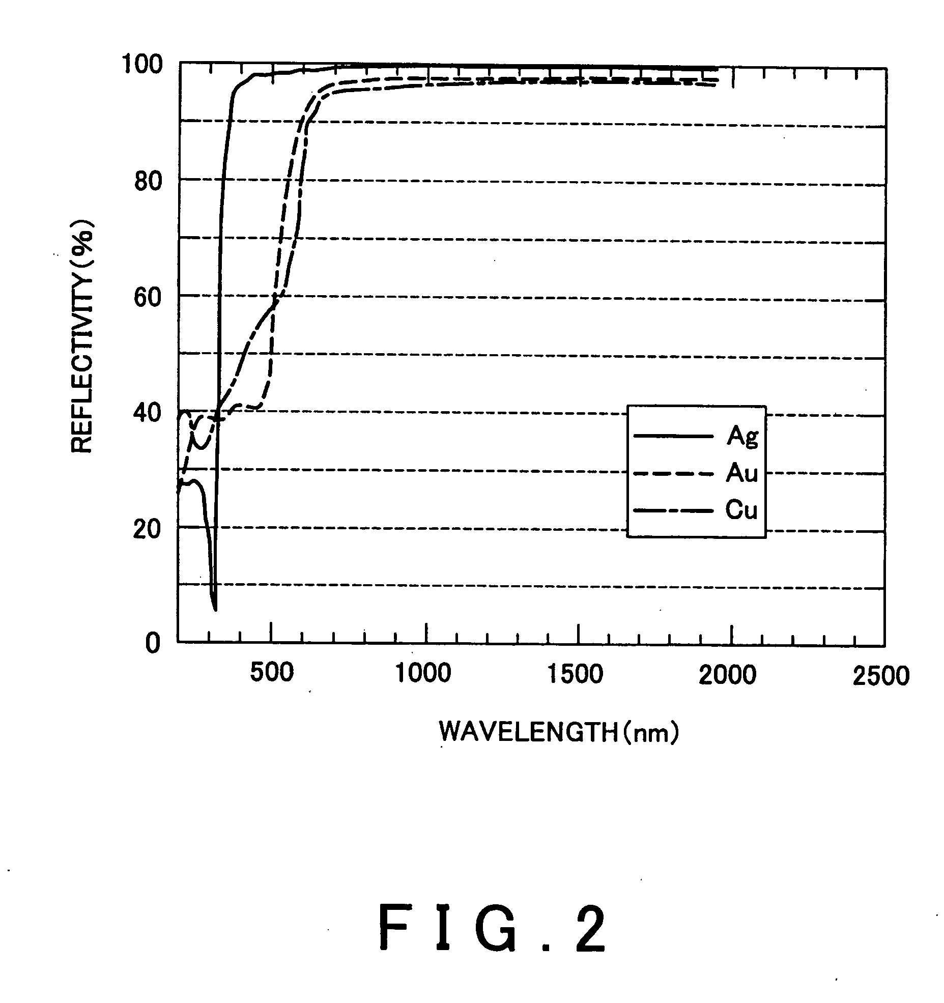
[0030] As a result of deliberate study on characteristics of metal dispersed and oriented in polarizing glass, the inventors et. al. of the present invention have found characteristics of metal that brings about polarizing glass that exhibits favorable polarizing characteristics in the whole RGB wavelength regions.

[0031] The characteristics of metal that brings about the polarizing glass exhibiting the favorable polarizing characteristics will be explained below.

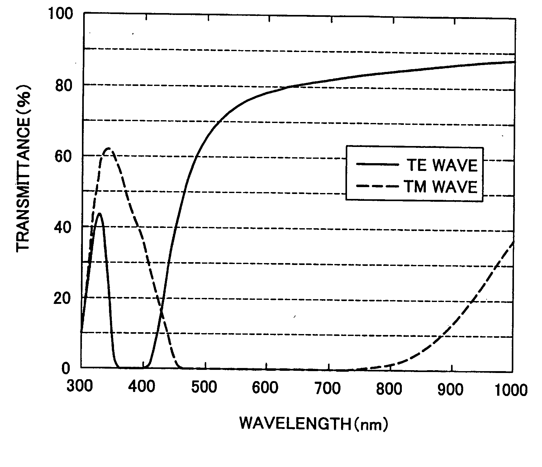
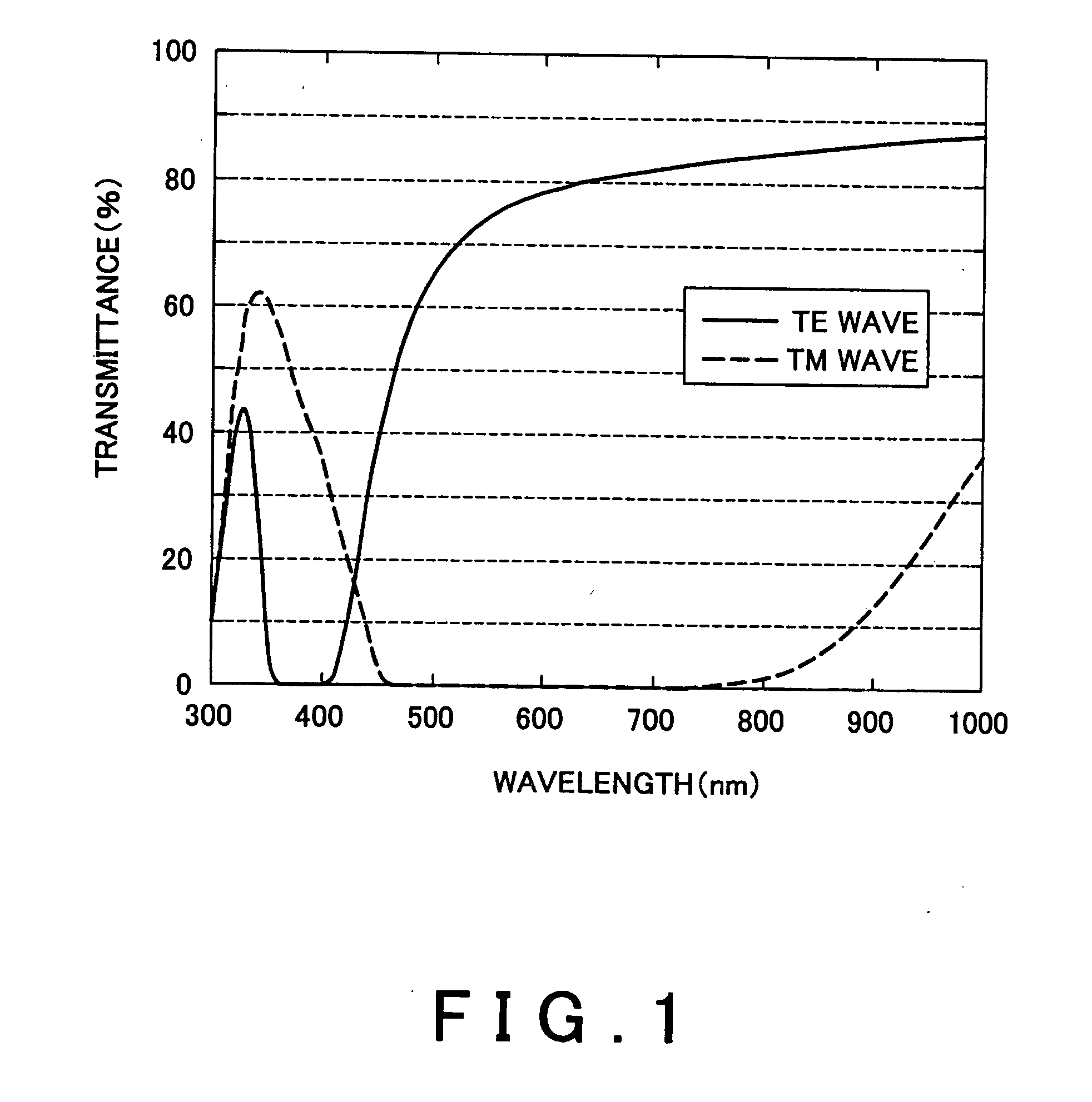
[0032] The polarizing glass utilizes dichroism of the metal dispersed and oriented within or on the surface of base glass. The dichroism is a nature of metal that a spectral absorption coefficient to linear polarized light having one optical...


PUM

PropertyMeasurementUnit
Transparencyaaaaaaaaaa
Absorption edgeaaaaaaaaaa
Energyaaaaaaaaaa

Abstract

In order to be able to obtain polarizing glass having favorable polarization characteristics in the visible light region, there is provided polarizing glass which is obtained by dispersing and orienting metal particles having anisotropy in shape within base glass and which exhibits dichroism, wherein the base glass is transparent glass whose absorption edge of incident light is 350 nm or less when wavelength is converted into a variable, a real number part of dielectric constant of the metal is minus or crosses over 0 with energy higher than 3.5 eV when the energy is converted into a variable and reflectivity of the metal is 80% or more in the visible light region.

Description

CROSS REFERENCE TO RELATED APPLICATION [0001] The present application claims priority from a U.S. Provisional Application No. 60 / 714,544 filed on Dec. 16, 2005, the contents of which are incorporated herein by reference.BACKGROUND OF THE INVENTION [0002] 1. Field of the Invention [0003] The present invention relates to polarizing glass that may be used for imaging apparatuses such as a liquid crystal TV receiver, a liquid crystal projector and the like. [0004] 2. Background Art [0005] While various types of polarizers for linearly polarizing light have been known, polarizing glass that is a polarizer made of glass, e.g., aluminoborosilicate glass, has been known as an absorption type polarizer, i.e., as what exhibits dichroism. The polarizing glass may be obtained by elongating glass containing metal particles such as silver and copper to elongate and orient the metal particles dispersed and contained in the glass into the shape of ellipsoid as disclosed in Japanese Patent Laid-Open...

Claims


Application Information

Patent Timeline
IPC IPC(8): G02B5/30
CPCC03C14/00G02B5/3083
Inventor MORIMOTO, SHOZOICHIMURA, MASAHIROAOKI, YUICH
Owner ARISAWA MFG CO LTD
Learn More