Method and apparatus for combining images

a technology of combining images and combining methods, applied in the field of x-ray equipment, can solve the problems of generating excess public health costs, drawbacks of the mammography tomosynthesis method and apparatus, and new methodologies that practitioners have little familiarity with, and have not yet been adopted

Inactive Publication Date: 2007-06-21
GENERAL ELECTRIC CO
View PDF12 Cites 53 Cited by
  • Summary
  • Abstract
  • Description
  • Claims
  • Application Information

AI Technical Summary

Benefits of technology

[0010] An embodiment of the invention is directed at overcoming the drawbacks of the techniques described above. An embodiment of the invention is directed to a transitional apparatus that combines the two applications in a single flow of operations. This transitional apparatus is, for example, a mammography apparatus, which is well known to practitioners, while at the same time possessing the characteristics of the now known tomosynthesis apparatus. This would enable speedier adoption than in the case of an entirely different technique. This transitional apparatus enables the simultaneous acquisition and examination of a standard projection radiography image and corresponding tomosynthesis projections. In other words, this transitional apparatus carries out two examinations in one. An embodiment of the invention then provides both a 2D image formation and a 3D image formation.

Problems solved by technology

This 2D image does not give sufficient information on the presence of a tumour or a case of calcification, and often gives rise to erroneous or false positive interpretations: this is often stressful to the patient and generates excess public health costs.
However, this now known mammography tomosynthesis method and apparatus has drawbacks.
These new methodologies, with which practitioners have little familiarity, have not yet been adopted.
This is chiefly due to the fact that these new methodologies have not been in existence for very long.
Moreover, the reliability of these new methods and apparatus is not proven.
However, the frequency of use of the now known mammography apparatus cannot be great as access to information requires more time since this information is sought sequentially in an image volume.
Another problem, which is more specific to mammography but could arise in other fields, is related to the need to be able to clinically analyze interesting micro-calcifications, sized from 100 μm to 500 μm.
This problem of spatial resolution is critically important in tomosynthesis mammography apparatus.
These now known method and apparatus thus cannot be used to obtain images of a quality sufficient to make a fine analysis of the micro-calcifications.

Method used


Image

  • Method and apparatus for combining images
  • Method and apparatus for combining images
  • Method and apparatus for combining images

Examples


Embodiment Construction

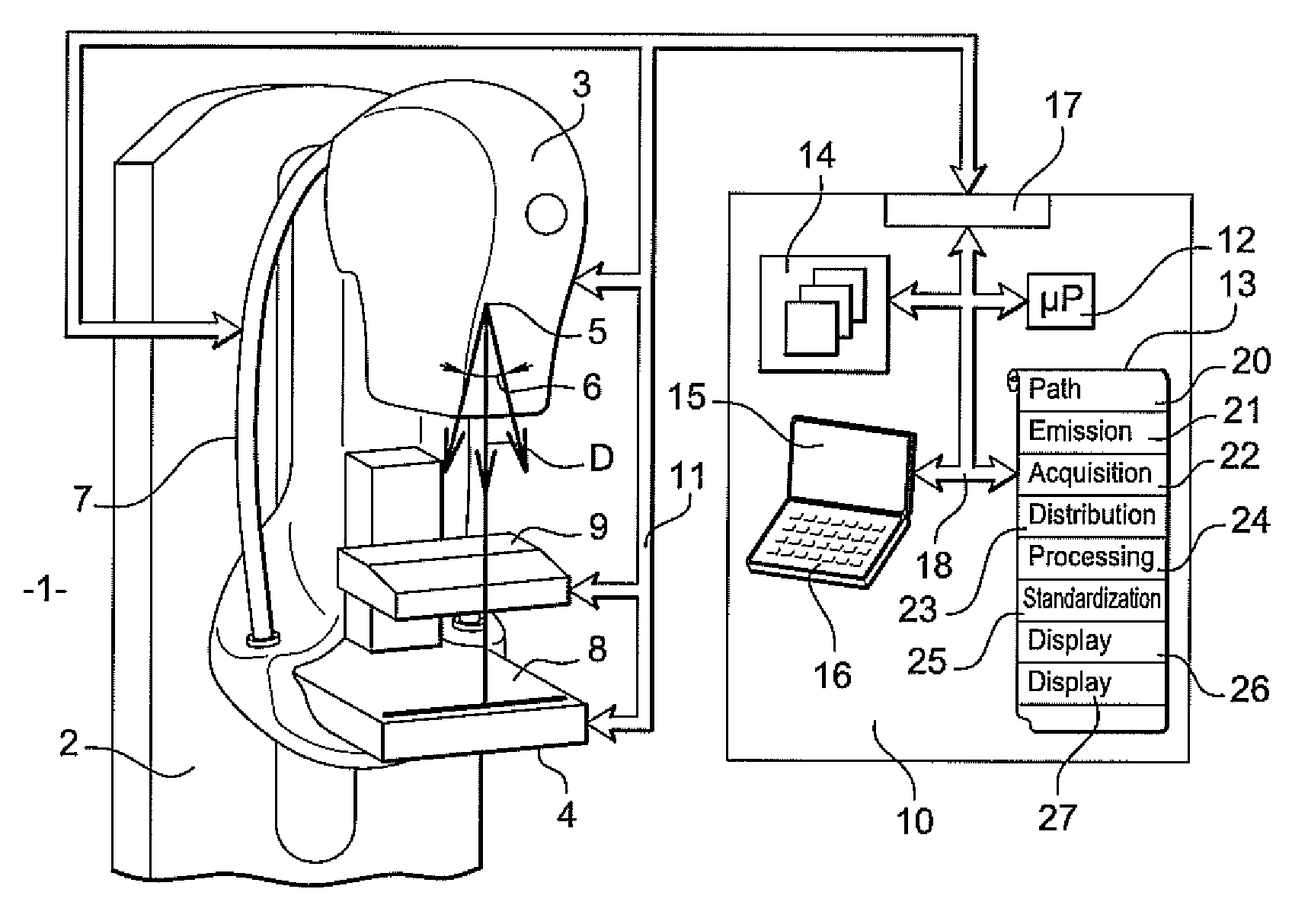
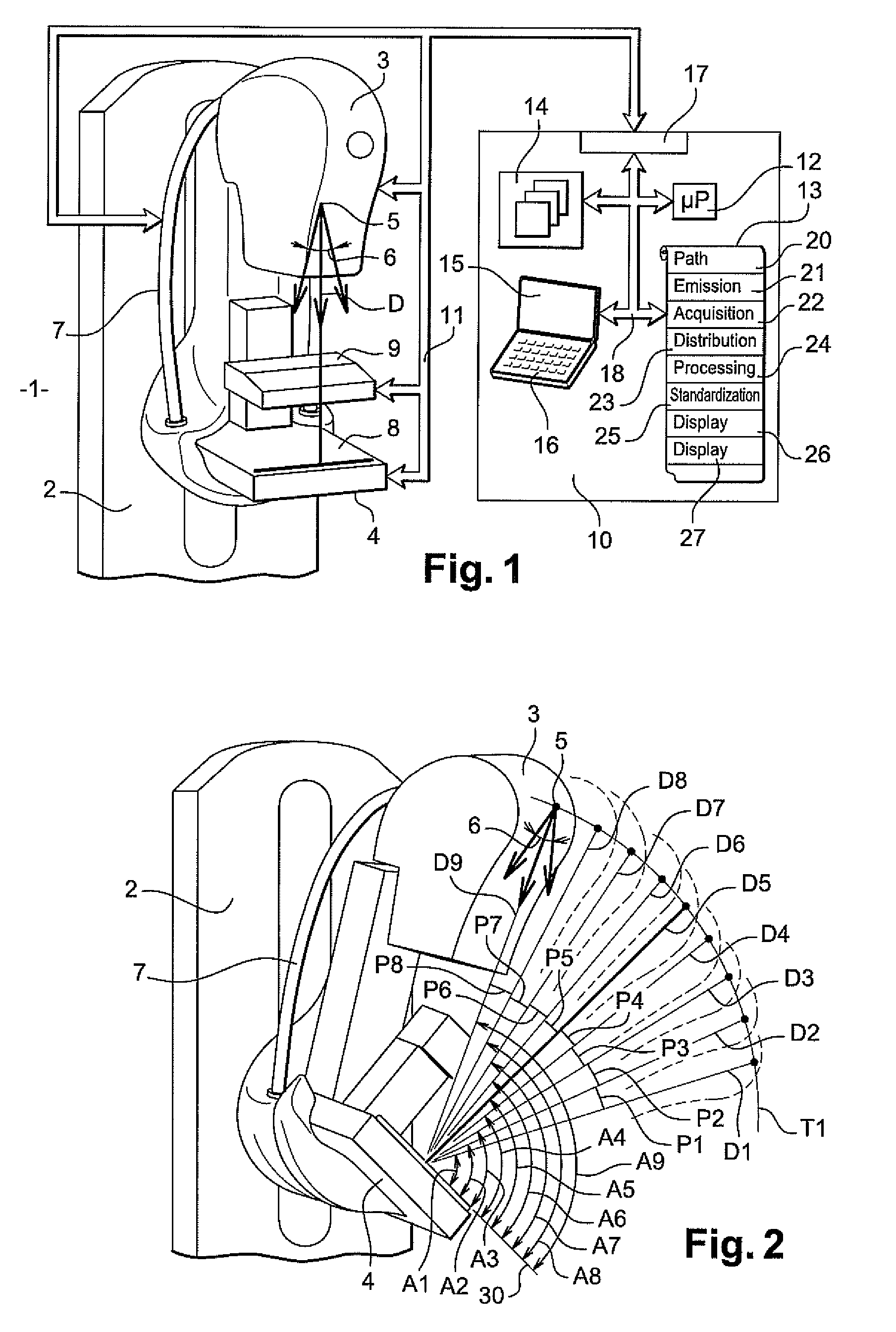
[0022]FIG. 1 shows a radiological apparatus, in particular a mammography apparatus. The mammography apparatus 1 has a vertical column 2. Vertical column 2 may be obliquely oriented. The apparatus 1 has an X-ray emitter tube 3 and a detector 4 capable of detecting the X-rays emitted by the tube 3. The tube 3 is provided with a focus 5 that is the X-ray emitting focus. This focus 5 emits an X-ray beam 6 along a main direction of emission D. The tube 3 is borne by an arm 7. An arch forms arm 7. The arm 7 is hinged on the vertical column 2 and can be used to shift the tube 3 along a path in the form of a circle arc. Other arrangements are possible, enabling the tube to move in a plane or in a sphere portion. The tube 3 can then take up different positions spread in a tilt between two extreme positions. These two positions are, for example, symmetrical to each other relative to the plane of the column 2.

[0023] The detector 4 can be an electronic detector or may be a detector with radios...


PUM


Abstract

An X-ray apparatus has a tube fitted out with an X-ray emitting focus that emits intensities of X-radiation crossing the object for a multiplicity of preliminarily determined main directions of emission, along a path. The apparatus shifts the X-ray tube along a path relative to the object. The apparatus has an X-ray detector that acquires a multiplicity of data of X-ray image data representing the multiplicity of main directions of emission. The apparatus distributes the preliminarily determined intensities of X-radiation non-uniformly on the multiplicity of main directions of emission. The apparatus also processes the multiplicity of data of X-ray image data in order to obtain both a 2D image and a 3D image of the object.

Description

CROSS-REFERENCE TO RELATED APPLICATIONS [0001] This application claims the benefit of a priority under 35 USC 119(a)-(d) to French Patent Application No. 05 052755 filed Sep. 13, 2005 the entire contents of which are hereby incorporated by reference. BACKGROUND OF THE INVENTION [0002] The present invention is directed to a method and apparatus for radiological imaging and in particular to an X-ray apparatus which, in an exemplary embodiment, is a mammography apparatus. The method and apparatus can be applied to but not exclusively in medical imaging and in non-destructive X-ray controls. [0003] An embodiment of the present the invention acquires at least one radiography image projection at the same time as a series of projections for tomosynthesis processing. An embodiment of the present invention improves the ergonomic of use of an X-ray apparatus to make it both simpler and faster to use. An embodiment of present invention is also directed to distributing intensities of X-radiatio...

Claims


Application Information

Patent Timeline
Patent Type & Authority Applications(United States)
IPC IPC(8): A61B6/04
CPCA61B6/02A61B6/466A61B6/502A61B6/5235
Inventor SOUCHAY, HENRI
Owner GENERAL ELECTRIC CO
Why Eureka
Try Eureka