

Image capturing apparatus with zoom function
a technology of zoom function and image capturing apparatus, which is applied in the field of image capturing apparatus, can solve problems such as unsatisfactory convenien
- Summary
- Abstract
- Description
- Claims
- Application Information
AI Technical Summary
Benefits of technology
Problems solved by technology
Method used
Image

Examples
first embodiment
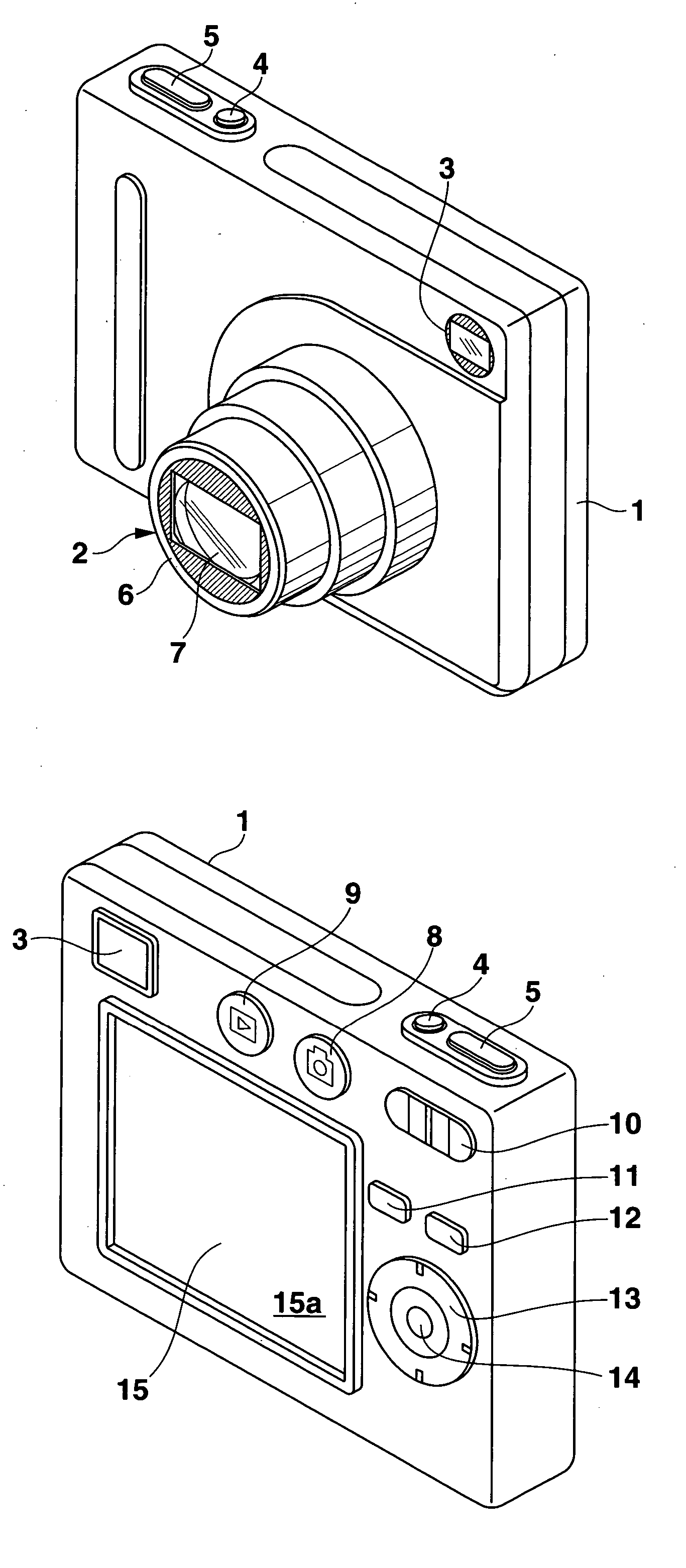
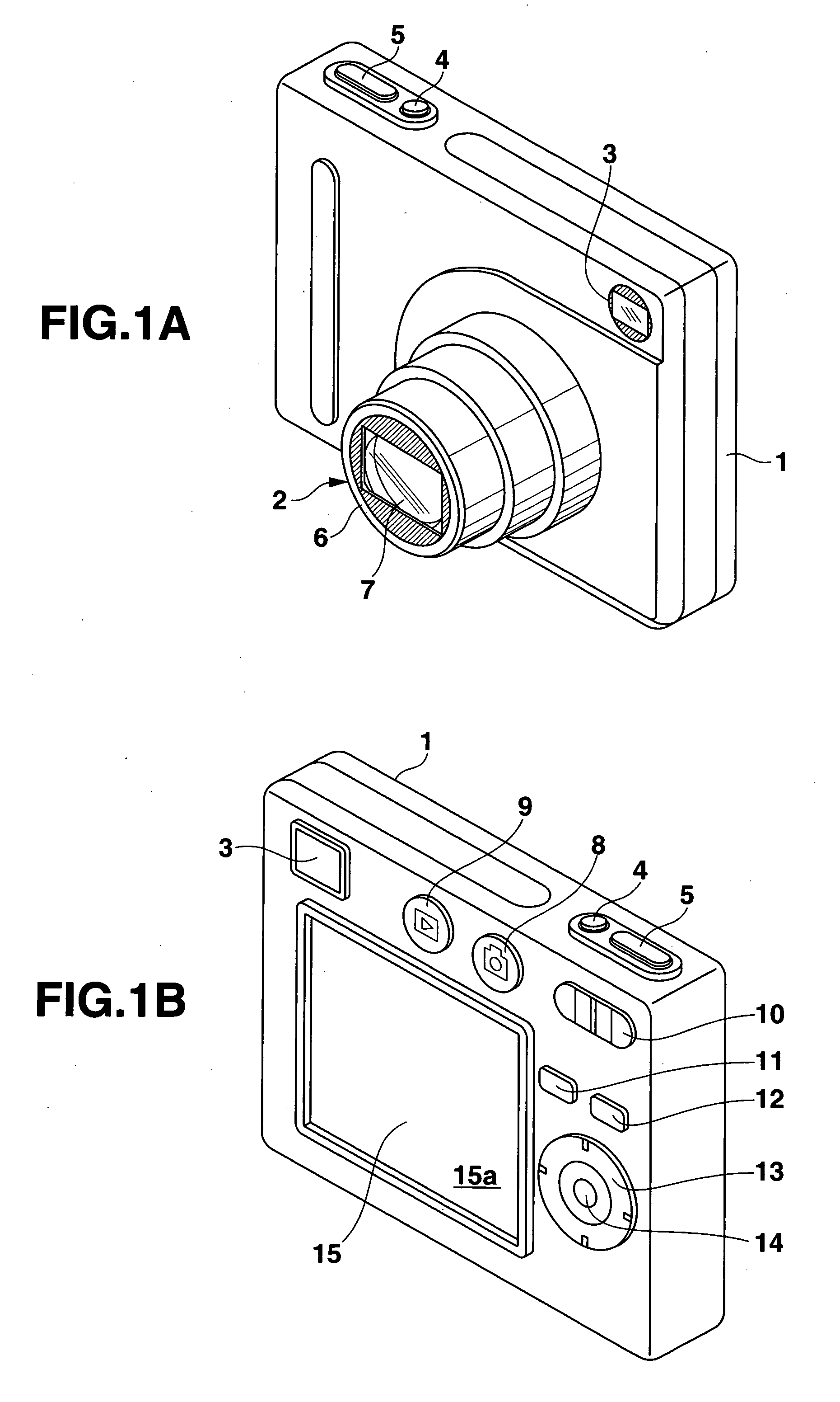
[0091]FIG. 1A is a front perspective view of a digital camera viewed from the upper side thereof according to embodiments of the invention. FIG. 1B is a rear perspective view of the digital camera viewed from the upper side thereof. The digital camera is equipped with a zoom function including both optical zoom and electronic zoom. The maximum magnification is treble “3×” for each of optical zoom and electronic zoom (“9×” when both are used). As shown in FIG. 1A, a lens unit 2 and an optical finder 3 are located on a substantially rectangular front face of a thin camera body 1. A power key 4 and a shutter key 5 are provided on a left side area of a top surface of the camera body 1.
[0092] The lens unit 2 is retractable and includes a lens barrel 6 and an image capturing lens system 7. The lens system 7 is provided in the multi-stage telescopic lens barrel 6, and is movable along the optical axis. The lens system 7 includes optical lenses such as a zoom lens and a focus lens. The len...
second embodiment
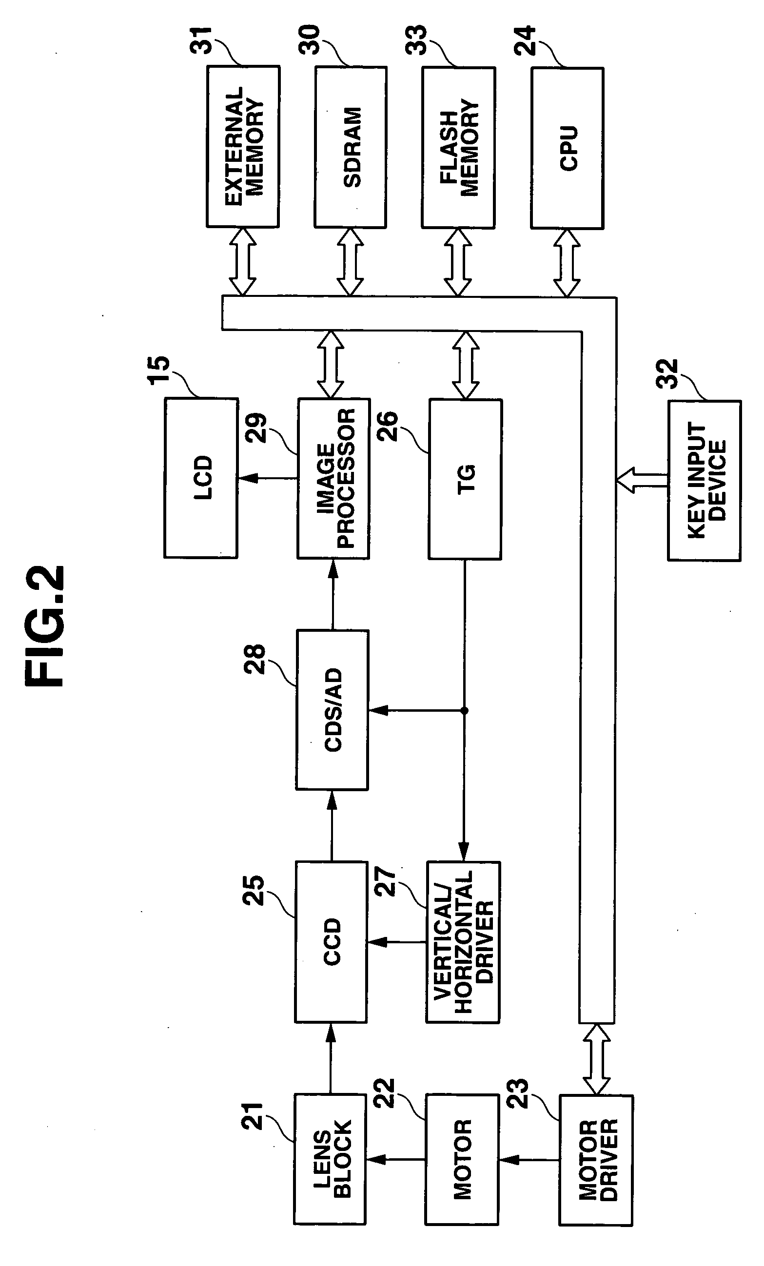
[0124] The second embodiment of the present invention will be described hereinafter. FIG. 6 is a flowchart of the direct zoom mode processing in the present embodiment executed by the CPU 24 of the digital camera having the configuration shown in FIGS. 1A, 1B and 2. The operation of the power key 4 turns the power on, and the operation of the REC key 8 starts the recording (image capturing) mode. Thereafter, the direct zoom mode processing can be selected.
[0125] In the direct zoom mode, the CPU 24 drives the CCD 25 at the predetermined through rate to capture the images of the object at the predetermined time intervals (step SB1) and executes the through image display processing (step SB2). The through image display processing is the same as the processing shown in FIG. 4 in the first embodiment. With the through image display processing, the images of the object including the through image 101 and the preview images 102, 103, and 104 are displayed on the display screen 15a as show...
third embodiment
[0138] The third embodiment of the present invention will be described hereinafter. FIG. 7 is a flowchart of the direct zoom mode processing in the present embodiment executed by the CPU 24 of the digital camera having the configuration shown in FIGS. 1A, 1B and 2. The operation of the power key 4 turns the power on, and the operation of the REC key 8 starts the recording (image capturing) mode. Thereafter, the direct zoom mode processing can be selected.
[0139] In the direct zoom mode, the CPU 24 drives the CCD 25 at the predetermined through rate to capture the images of the object at the predetermined time intervals (step SC1) and executes the through image display processing (step SC2). The through image display processing is the same as the processing shown in FIG. 4 in the first embodiment. By the through image display processing, the images of the object including the through image 101 and the preview images 102, 103, and 104 are displayed on the display screen 15a as shown i...
PUM
 Abstract
Description
Claims
Application Information