Pulley assembly and method

a technology of pulleys and components, applied in the direction of gearing elements, belts/chains/gearrings, hoisting equipments, etc., can solve the problems of heavy materials and the fact that the pulleys composed of such materials are also relatively heavy

Inactive Publication Date: 2007-06-21
GM GLOBAL TECH OPERATIONS LLC
View PDF7 Cites 60 Cited by
  • Summary
  • Abstract
  • Description
  • Claims
  • Application Information

AI Technical Summary

Benefits of technology

[0004] The pulley assembly of the present invention includes a ring portion having a radially outer frictional surface, and a radially inner ring flange defining a plurality of ring teeth. The pulley assembly also includes a hub integrally formed onto the ring portion. The hub has a peripheral hub flange that includes a top portion and a bottom portion configured to trap the ring flange therebetween. The hub flange is also configured to engage ...

Problems solved by technology

Cast iron and steel are, however, relatively heavy materials and ...

Method used


Image

  • Pulley assembly and method
  • Pulley assembly and method
  • Pulley assembly and method

Examples


Embodiment Construction

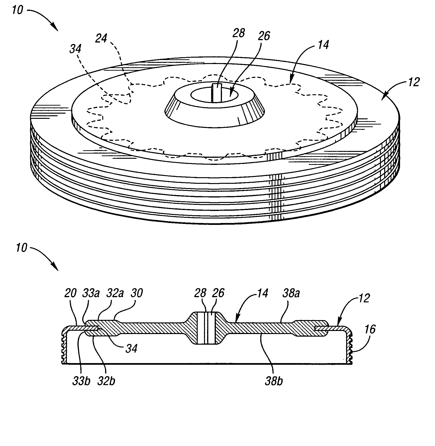
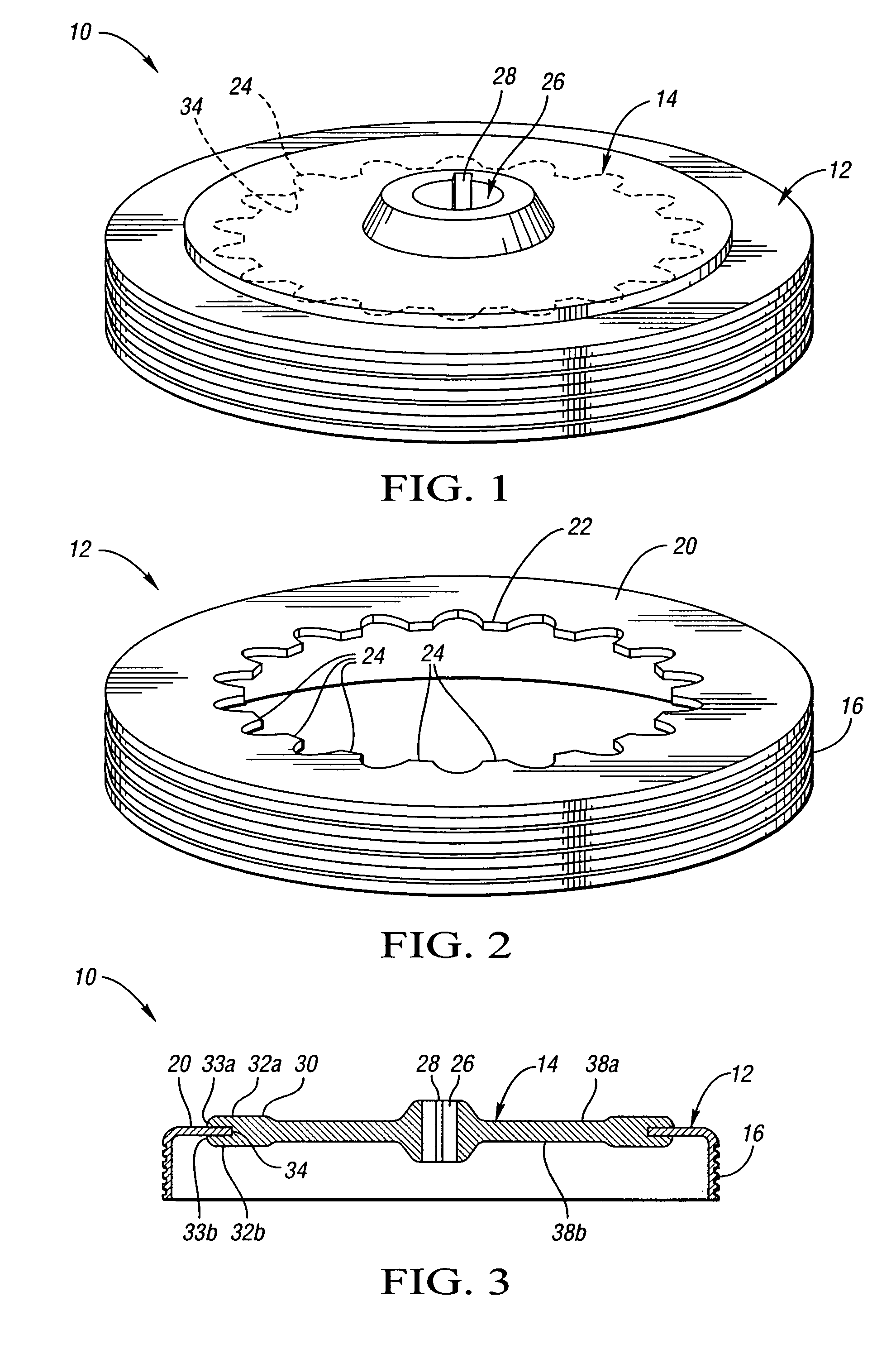
[0012] Referring to the drawings, wherein like reference numbers refer to like components, FIG. 1 shows a perspective view of a pulley assembly 10 in accordance with the present invention. The pulley assembly 10 includes a radially outer ring portion 12 and a radially inner hub 14 circumscribed by the ring portion 12. The pulley assembly 10 will hereinafter be described as a pulley assembly for an automotive accessory drive system; however, it should be appreciated that the pulley assembly 10 of the present invention is configured for other applications as well.

[0013] Referring to FIG. 2, the ring portion 12 is shown in more detail. The ring portion 12 includes a radially outer frictional surface 16 adapted for engagement by a device such as a belt (not shown). According to an embodiment wherein the frictional surface 16 is engaged by a belt, the belt may be of any known type including a belt having a generally rectangular cross-section or a belt having a v-shaped or triangular cro...


PUM


Abstract

The apparatus of the present invention provides an improved pulley assembly. The pulley assembly includes a ring portion having a frictional surface and a radially inner ring flange defining a plurality of ring teeth. The pulley assembly also includes a hub integrally formed onto the ring portion. The hub has a peripheral hub flange that includes a top portion and a bottom portion configured to trap the ring flange therebetween. The hub flange is also configured to engage the ring teeth and thereby prevent rotation of the hub relative to the ring portion. The ring portion is preferably composed of a first material such as steel or cast iron, and the hub is preferably composed of a second material such as aluminum or magnesium that is lighter by volume than the first material. Accordingly, the overall weight of the pulley assembly is less than that of a comparable pulley assembly composed entirely of steel or cast iron.

Description

CROSS-REFERENCE TO RELATED APPLICATIONS [0001] This application claims priority to U.S. Provisional Patent Application No. 60 / 739,578 filed on Nov. 23, 2005.TECHNICAL FIELD [0002] The present invention pertains generally to an improved pulley assembly and method for producing a pulley assembly. BACKGROUND OF THE INVENTION [0003] It is well known to implement pulleys to transfer rotational energy from one device to another. Conventional pulleys are typically composed of cast iron or steel to support heavy loads and to resist wear. Cast iron and steel are, however, relatively heavy materials and pulleys composed of such materials are therefore also relatively heavy. SUMMARY OF THE INVENTION [0004] The pulley assembly of the present invention includes a ring portion having a radially outer frictional surface, and a radially inner ring flange defining a plurality of ring teeth. The pulley assembly also includes a hub integrally formed onto the ring portion. The hub has a peripheral hub ...

Claims


Application Information

Patent Timeline
IPC IPC(8): F16H55/49
CPCF16H55/36F16H55/44F16H55/49
Inventor KLEBER, RICHARD M.
Owner GM GLOBAL TECH OPERATIONS LLC
Why Eureka
Try Eureka