System and method for generating a patient clinical status indicator

a clinical status indicator and system technology, applied in the field of patient monitoring, can solve the problems of affecting the timely detection of patient parameters, affecting the quality of care of patients, and voluminous caregivers,

Inactive Publication Date: 2007-06-21
BERNOULLI ENTERPRISE INC
View PDF6 Cites 50 Cited by
  • Summary
  • Abstract
  • Description
  • Claims
  • Application Information

AI Technical Summary

Benefits of technology

[0005] In one embodiment, the patient clinical status indicator is a risk indicator. In another embodiment the patient clinical status indicator is a predictive outcomes indicator. In still another embodiment, the system communicates medical device alerts and alarms to the display. In yet another embodiment the patient clinical status indicator is generated in response to a plurality of weighing coefficients, each associated with a patient parameter. In one embodiment the plurality of patient parameters include temperature, blood pressure, respiration rate, blood oxygen, respiration volume, and pulse rate. In another embodiment the patient clinical status indicator is calculated from a polynomial which includes one or more of the plurality of patient parameters and a plurality of coefficients. Each of the coefficients is associated with a respective parameter.

Problems solved by technology

As a result, especially in critical care environments, the amount of data, much of which is time-sensitive, presented to the caregiver is voluminous and as a result the caregiver may not notice trends, or changes in the patient's parameters in a timely, clinically relevant manner.

Method used


Image

  • System and method for generating a patient clinical status indicator
  • System and method for generating a patient clinical status indicator

Examples


Embodiment Construction

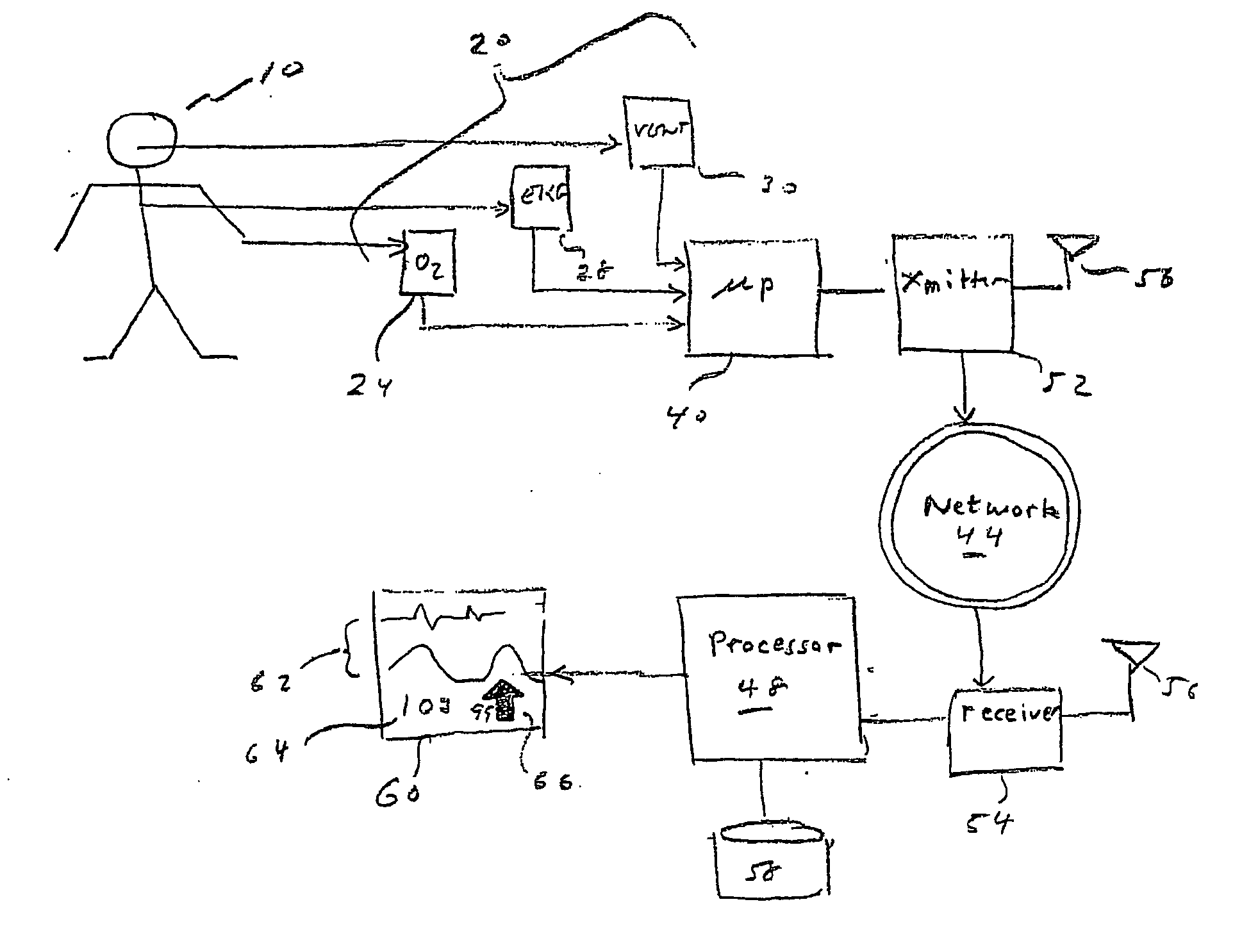
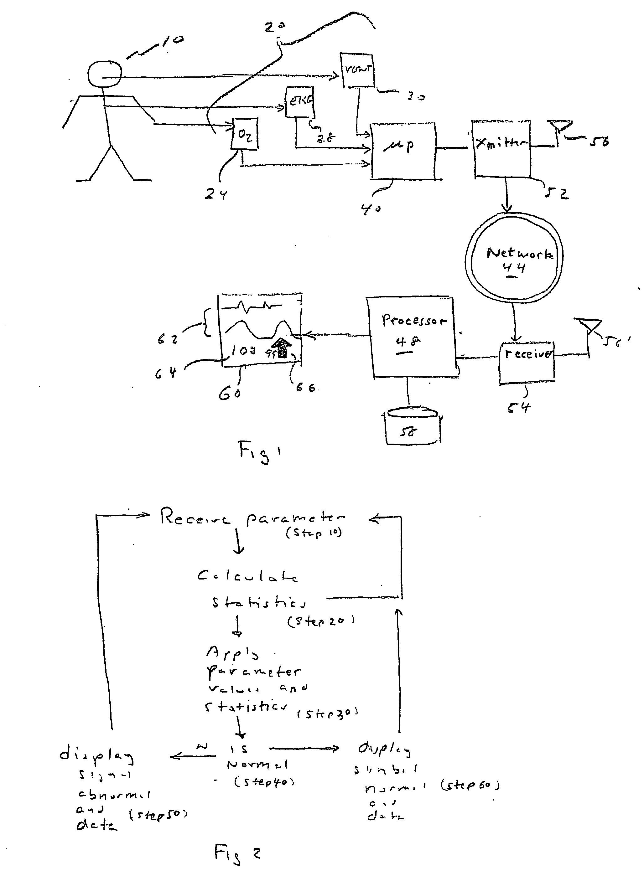
[0010] In brief overview and referring to FIG. 1, a patient 10 is monitored by a number of physiologic patient monitors, generally 20. These monitors can include one or more of oxygen sensors 24, carbon dioxide and other metabolic sensors, electrocardiogram (cardiac) 28, hemodynamic (e.g., blood pressure, pulse pressure, blood volume, and blood flow) monitors and ventilation / respiratory monitor 30. Each of these monitors 20 produces one or more signals which are input signals to a processor 40. These signals are processed and either transmitted over a network 44 to a host processor 48 or communicated to a transmitter 52 which broadcasts the signals to a receiver 54 by way of antennae 56, 56′. In one embodiment the network is hard-wired rather than wireless. The host processor 48 performs calculations on the signals and then transmits the results to a display 60. The display 60 displays the results of the calculations including the original signals 62, a numerical score 64 and a tren...


PUM


Abstract

A system and method for displaying a patient clinical status indicator. In one embodiment the system includes a plurality of sensors, each sensor measuring a respective patient parameter; a processor in communication with each of the plurality of sensors, and a display in communication with the processor. The processor receives the patient parameters and generates a patient clinical status indicator in response to the plurality of patient parameters. The display displays the patient clinical status indicator. In one embodiment the patient clinical status indicator is a risk indicator. In one embodiment, the method includes the steps of measuring a plurality of patient parameters; generating a patient clinical status indicator in response to the plurality of patient parameters; and displaying the patient clinical status indicator. In another embodiment the step of generating the patient clinical status indicator further uses a plurality of weighing coefficients each associated with a respective patient parameter.

Description

FIELD OF THE INVENTION [0001] The invention relates generally to the field of patient monitoring and more specifically to the field of data analysis used in patient monitoring. [0002] This application claims priority to U.S. Provisional Patent Application 60 / 750,533 filed on Dec. 15, 2005, the disclosure of which is herein incorporated by reference in its entirety. [0003] There are a multitude of patient parameters available to the clinician or care provider for monitoring. Many of the parameters comprise real-time physiologic monitoring of the patient. As a result, especially in critical care environments, the amount of data, much of which is time-sensitive, presented to the caregiver is voluminous and as a result the caregiver may not notice trends, or changes in the patient's parameters in a timely, clinically relevant manner. The present invention provides a solution to this problem. SUMMARY OF THE INVENTION [0004] The invention relates in one aspect to a system for displaying a...

Claims


Application Information

Patent Timeline
Patent Type & Authority Applications(United States)
IPC IPC(8): A61B5/00A61B5/02A61B5/08
CPCA61B5/0205A61B5/024A61B5/026A61B5/029A61B5/0402A61B5/08A61B5/145G06F19/3418G06F19/345G16H50/20G16H50/30G16H40/67A61B5/318
Inventor BIONDI, JAMES W.
Owner BERNOULLI ENTERPRISE INC
Why Eureka
Try Eureka