
Multi paint roller connector

Inactive Publication Date: 2007-06-28
KIM SONG
View PDF18 Cites 22 Cited by
  • Summary
  • Abstract
  • Description
  • Claims
  • Application Information

AI Technical Summary

Benefits of technology

[0011] The present invention responds to complaints often made by painters as single rollers do not carry enough paint, and time is wasted in dipping the paint rollers. This will benefit painters due to less dipping time and more painting time. Moreover, painters will save time with the use of multi-rollers because it will allow a larger surface to be painted than with a single roller.
[0012] Moreover, the present invention enables a painter to use a low density, or high porosity, paint roller and high density paint roller in one step, by providing a low density paint roller as one of the rollers and a high density paint roller as the other roller. This allows the painter to avoid double rolling the surface by carrying sufficient paint on the one roller to cover a desirable surface area and using the other, high density, roller to provide a very smooth finish.

Problems solved by technology

While a wide variety of structures are provided by the foregoing prior art, and some of them are fairly simple in structure, none provide a completely satisfactory solution to the economics of paint roller manufacture which requires not only low cost but also effective and secure construction that can be used with a widely available commercial paint rollers.
It is often desirable to use a high density foam roller to obtain a very smooth finish, but such rollers do not have the porosity to carry sufficient paint.

Method used


Image

  • Multi paint roller connector
  • Multi paint roller connector
  • Multi paint roller connector

Examples


Embodiment Construction

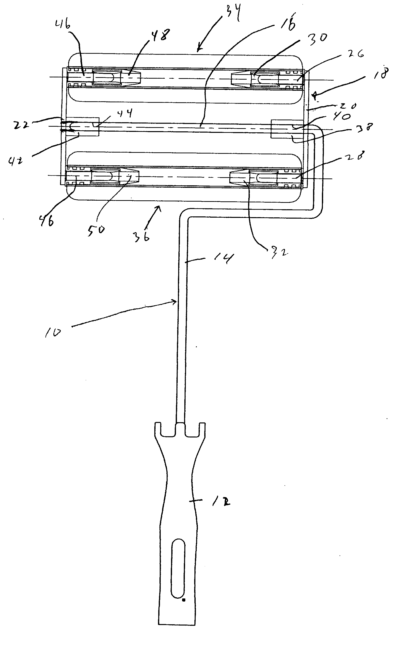
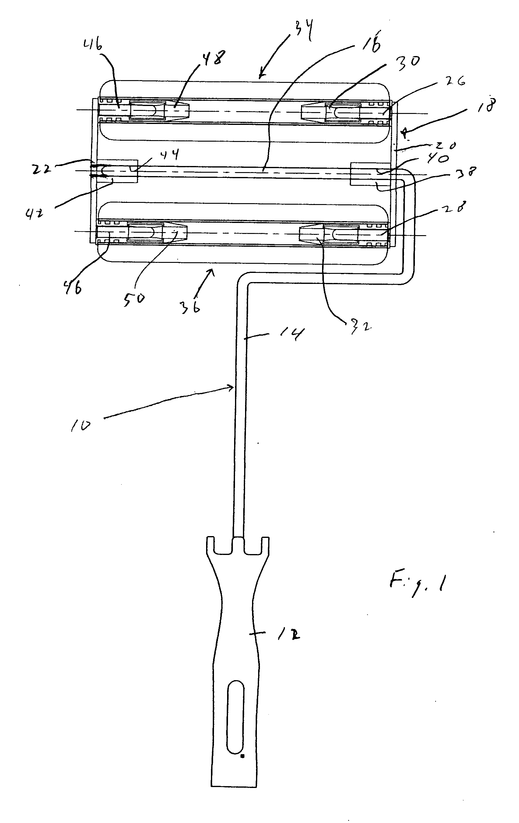
[0026] Referring to FIG. 1, an assembly is shown comprising a more or less standard type paint roller frame 10 consisting of a handle 12 carrying a wire frame 14 that is bent in return fashion and terminates with a shaft 16. The shaft 16 is connected to a bracket assembly 18 which consist of a proximal bracket 20 and a distal bracket 22.

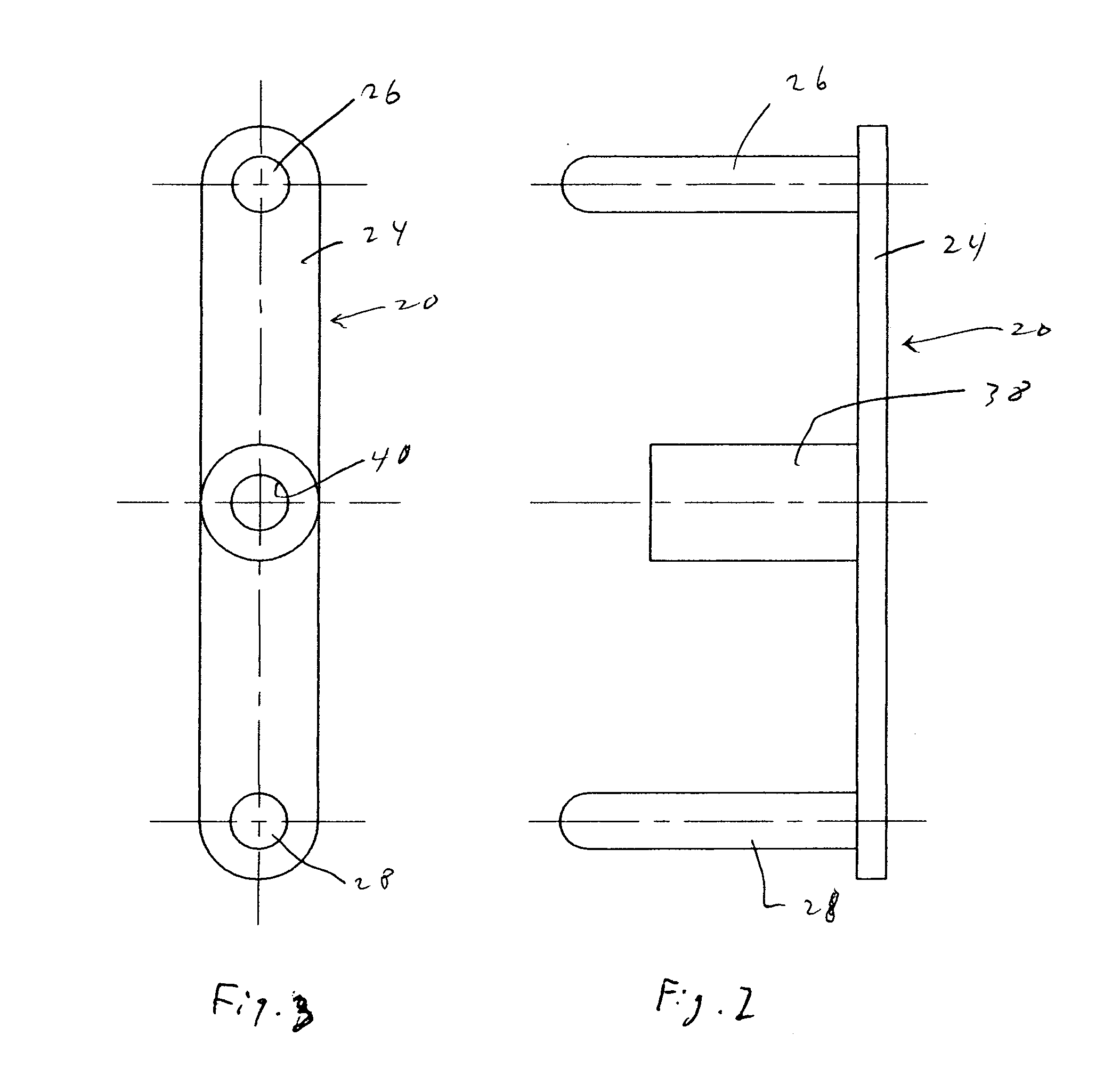
[0027] Referring additionally to FIGS. 2 and 3, the proximal bracket 20 consists of a mounting plate 24 and a pair of cylindrical roller engaging shafts 26 and 28 integral with and extending normal to the mounting plate 24 on opposite ends thereof. The roller engaging shafts 26 and 28 each has an outer diameter substantially the same as the diameter of the paint roller frame shaft 16. This enables it to engage shaft receiving roller bearings, respectively 30 and 32, carried internally on the ends of a pair of mini-rollers, respectively 34 and 36.

[0028] The proximal bracket 20 has a member 38 integral with and extending normal to the mounting plate ...


PUM


Abstract

A bracket for mounting one or more paint rollers to the shaft of a paint roller frame. A mounting plate carries a pair of roller engaging members extending normal to the mounting plate on opposite ends thereof, each roller engaging member being formed to rollingly engage an end of a paint roller. A shaft engaging member is located between the pair of roller engaging members and has a shaft opening formed there through of a dimension, and arranged, to pivotally receive the shaft of a paint roller frame. In one embodiment, one or more mini-rollers, with internal roller bearings, are carried on shafts integral with and extending from opposing mounting brackets. In other embodiments, two or three standard paint rollers are carried on members that extend from opposing mounting brackets and are rotatable thereon. In further embodiments, a first roller is formed with a surface material that has sufficient nap or a sufficiently low density or porosity to carry an amount of paint sufficient to cover a desired area of surface to be painted, and a second roller is formed with a surface material of a sufficiently high density to provide a smooth finish to said surface area.

Description

FIELD OF THE INVENTION [0001] The present invention relates generally to an apparatus for painting and in particular to a mounting bracket for paint rollers. BACKGROUND OF THE INVENTION [0002] A variety of paint roller assemblies are available, typically comprising a handle carrying a frame, usually of metal, pivotally connected to a paint roller for applying paint to a surface. Many of these paint roller assemblies include a single paint roller, others include a plurality of paint rollers for purposes of reducing the number of strokes required to cover a surface of paint, for catching dripping paint on to a secondary roller, to transfer paint from one roller to another, for example, stencil, paint roller, and the like. Representative prior art includes United States Patent Publication Nos. 2005 / 0091778, entitled “Paint Roller Assembly,” 2002 / 0122893, entitled “Dual Spindle Paint Roller,” and U.S. Pat. No. 6,045,282 entitled “Multi-Roller Paint Applicator System,” U.S. Pat. No. 6,21...

Claims


Application Information

Patent Timeline
IPC IPC(8): B05C17/02
CPCB05C17/0217B05C17/023
Inventor KIM, SONG
Owner KIM SONG
Learn More