Method Of Manufacturing Ink-Jet Head

a manufacturing method and inkjet technology, applied in the direction of ink apparatus, piezoelectric/electrostrictive transducers, transducer types, etc., can solve the problems of defective contact between the piezoelectric body and the fpc, the piezoelectric body cannot be sufficiently spaced apart from each other, and the manufacturing cost increase, so as to reduce the manufacturing cost and reduce the warping of the piezoelectric body , the effect of sufficient spa

Active Publication Date: 2007-06-28
BROTHER KOGYO KK
View PDF2 Cites 7 Cited by
  • Summary
  • Abstract
  • Description
  • Claims
  • Application Information

AI Technical Summary

Benefits of technology

[0006] An object of the present invention is to provide a method of manufacturing an ink-jet head that can ensure a sufficient space between a piezoelectric body and a wire member while preventing occurrence of warping of the piezoelectric body, deterioration in insulation resistance of the piezoelectric body, and cracking in the piezoelectric body.
[0008] In the aspect, the land is made of the resin paste. It is therefore not necessary to bake the land at a high temperature when forming the land. This can suppress warping of the piezoelectric body, and scattering of a conductive material included in the land into the piezoelectric body which deteriorates insulation resistance of the piezoelectric body. In addition, since the land is made of the resin paste, manufacturing costs can be reduced as compared with when the land is made of a metal material such as gold.
[0009] Besides, since the land is formed on the piezoelectric actuator before the piezoelectric actuator is bonded to the passage unit, the land can be formed under a state where the whole of the face of the piezoelectric actuator opposite to a face thereof formed with the land is supported on the support member. This makes it difficult that cracking occurs in the piezoelectric body.
[0010] Moreover, when bonding the piezoelectric actuator to the passage unit, the land is pressed except a part thereof. Therefore, the part of the land is not crushed due to a bonding press. Thus, the part of the land is not reduced in height, so that a sufficient space is ensured between the piezoelectric body and the wire member. This can prevent ejection failure which may otherwise be caused by occurrence of contact between the wire member and the piezoelectric body.
[0012] Still further, when bonding the piezoelectric actuator to the passage unit, the piezoelectric body is not directly pressed but indirectly pressed with the land therebetween. Therefore, even if a small foreign matter exists between the piezoelectric body and the jig or a small protrusion exists on the surface of the piezoelectric body, occurrence of cracking or the like in the piezoelectric body can be prevented.

Problems solved by technology

In addition, since a material such as gold is expensive, manufacturing costs increase.
As a result, the piezoelectric body and the FPC cannot sufficiently be spaced apart from each other.
Such a land may become a defective contact.
In a case where, like this, the lower face of the piezoelectric actuator is partially supported on the passage unit, cracking may occur in the piezoelectric body due to force that is applied to the piezoelectric body at the time of printing the resin paste in a pattern on surfaces of the individual electrodes.

Method used


Image

  • Method Of Manufacturing Ink-Jet Head
  • Method Of Manufacturing Ink-Jet Head
  • Method Of Manufacturing Ink-Jet Head

Examples


Embodiment Construction

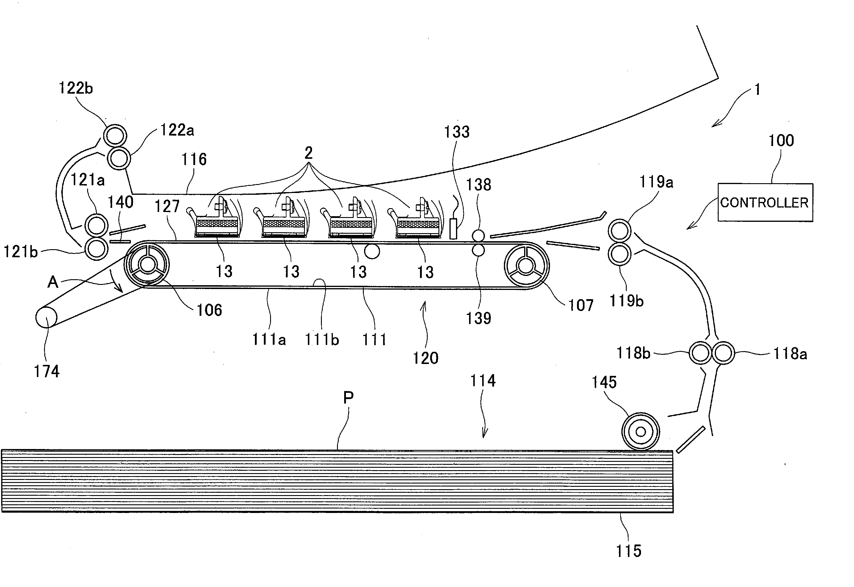
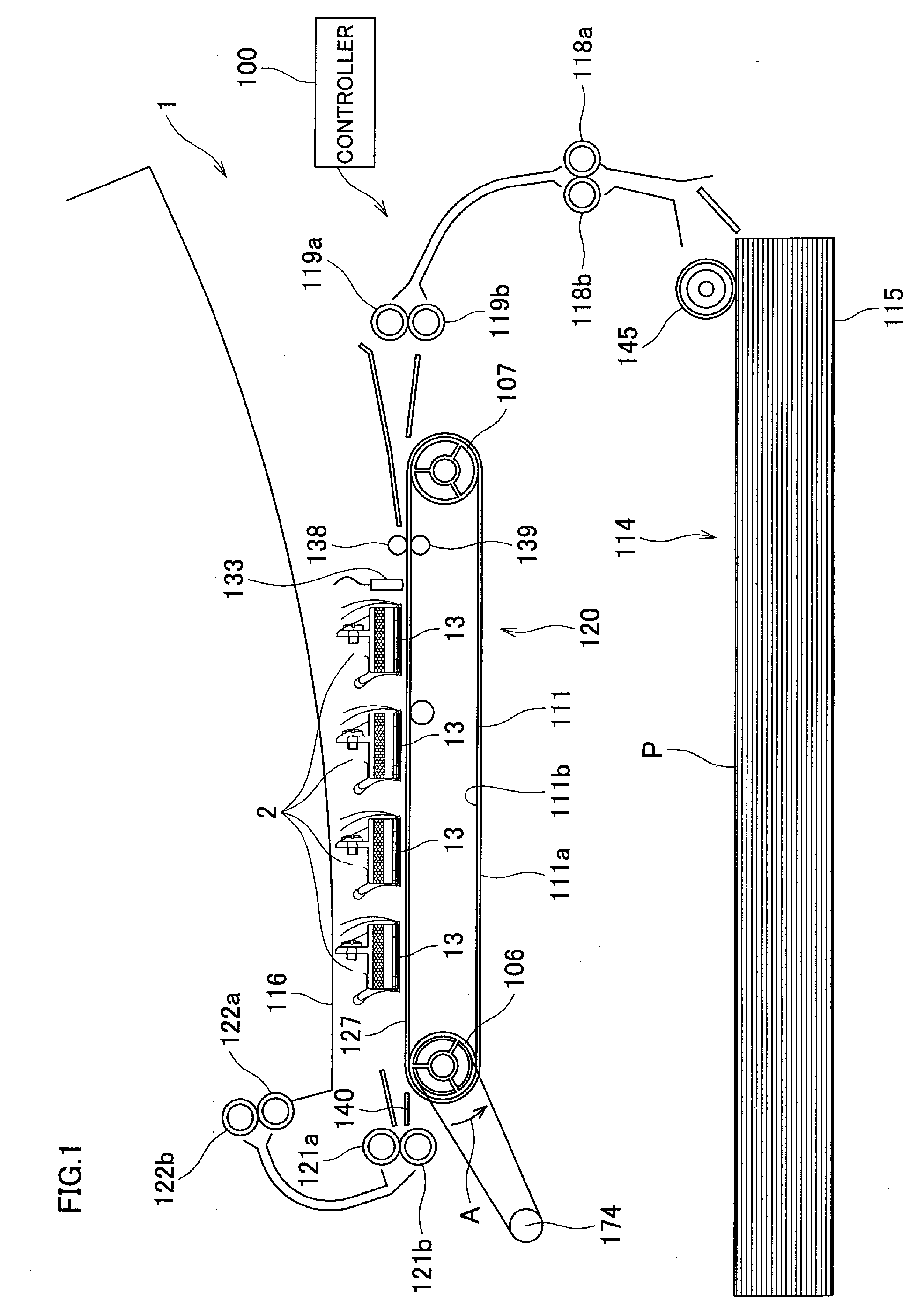
[0025] A description will be given to an ink-jet head manufactured by a method according to an embodiment of the present invention. FIG. 1 illustrates a printer 1 that includes ink-jet heads 2 manufactured by the method according to this embodiment. The printer 1 illustrated in FIG. 1 is a color ink-jet printer of line-head type, which includes four fixed ink-jet heads 2. In a plan view, the ink-jet head 2 has a rectangular shape elongated in a direction perpendicularly crossing the drawing sheet of FIG. 1. The printer 1 includes a paper feed unit 114, a paper discharge tray 116, and a conveyance unit 120, which are shown in lower, upper, and middle parts of FIG. 1, respectively. The printer 1 also includes a controller 100 that controls operations of the above-mentioned units.

[0026] The paper feed unit 114 has a paper holder 115 and a paper feed roller 145. A stack of printing papers (recording media) P of rectangular shape can be held in the paper holder 115. The paper feed rolle...


PUM

PropertyMeasurementUnit
thicknessaaaaaaaaaa
thicknessaaaaaaaaaa
thicknessaaaaaaaaaa

Abstract

There is provided a method of manufacturing an ink-jet head comprising a passage unit, a piezoelectric actuator, and a wire member. The passage unit has a surface on which a pressure chamber is provided in a form of a recess. The piezoelectric actuator includes a piezoelectric body that closes the recess, an electrode that is formed on the piezoelectric body, and a conductive land that is formed on the electrode. The wire member includes a wiring provided thereon with a terminal electrically connected to the land. The method comprises the steps of forming on the electrode a land made of a resin paste, bonding the passage unit and the piezoelectric actuator to each other by pressing the land except a part thereof in a state where the electrode is opposed to the pressure chamber, and electrically connecting the land to the terminal by bringing the part of the land not pressed in the step of bonding into contact with the wire member.

Description

BACKGROUND OF THE INVENTION [0001] 1. Field of the Invention [0002] The present invention relates to a method of manufacturing an ink-jet head that ejects ink from an ink ejection port. [0003] 2. Description of Related Art [0004] A known ink-jet head has a passage unit and a piezoelectric actuator bonded to the passage unit. The passage unit has an individual ink passage including an ink ejection port and a pressure chamber. The piezoelectric actuator applies pressure to ink contained in the pressure chamber. In some ink-jet heads of this type, on a surface of a piezoelectric actuator, an electrode is electrically connected to a wire member through which a drive signal is supplied to the electrode so that the piezoelectric actuator is driven. For example, U.S. Patent Application Publication No. 20040113994 discloses an ink-jet head in which an actuator unit acting as a piezoelectric actuator includes a piezoelectric body having four laminated piezoelectric layers, and conductive lan...

Claims


Application Information

Patent Timeline
Patent Type & Authority Applications(United States)
IPC IPC(8): B21D53/76B41J2/045B41J2/055B41J2/135B41J2/14B41J2/145B41J2/155B41J2/16
CPCB41J2/14209B41J2002/14217B41J2002/14225B41J2002/14306Y10T29/49401B41J2002/14491B41J2202/20Y10T29/42B41J2002/14459
Inventor HIROTA, ATSUSHISAKAIDA, ATSUO
Owner BROTHER KOGYO KK
Why Eureka
Try Eureka