Twin-clutch device

a twin-clutch, axial direction technology, applied in the direction of fluid-actuated clutches, clutches, non-mechanical actuated clutches, etc., can solve the problem of increasing the size of the twin-clutch device in the axial direction

Active Publication Date: 2007-06-28
HONDA MOTOR CO LTD
View PDF5 Cites 10 Cited by
  • Summary
  • Abstract
  • Description
  • Claims
  • Application Information

AI Technical Summary

Benefits of technology

[0014] According to an embodiment of the present invention, the second clutch disconnection / connection control mechanism is arranged between the first and second clutch inners respectively provided to the first and second clutch actuating mechanisms that are arranged coaxially side by side. At least a part of the second clutch disconnection / connection control mechanism is accommodated in at least one of the first and second cylinder portions respectively provided to the first and second clutch inners. Accordingly, the second clutch disconnection / connection control mechanism can be arranged by effectively utilizing the dead space between the first and second cylinder portions, and the first and second driven shafts, thereby allowing the two-clutch device to be made more compact with respect to the axial direction.
[0015] Further, according to an embodiment of the present invention, the first and second clutch disconnection / connection control mechanisms are arranged radially inward with respect to the first and second cylinder portions constituting part of the first and second clutch inners respectively provided to the first and second clutch actuating mechanisms that are arranged coaxially side by side. Accordingly, the first and second clutch disconnection / connection control mechanisms can be arranged by effectively utilizing the dead space formed between the first and second cylinder portions, and the first and second driven shafts, whereby the two-clutch device can be made more compact with respect to the axial direction. In addition, the inertial mass of the twin-clutch device can be reduced, thus allowing power from the drive source to be transmitted without causing a decrease in responsiveness.
[0016] According to an embodiment of the present invention, the hydraulic pressure chamber and urging-member accommodating chamber of the first clutch disconnection / connection control mechanism for switching disconnection / connection of the first clutch actuating mechanism, which is arranged axially outward with respect to the second clutch actuating mechanism, are arranged radially inward with respect to the first cylinder portion of the first clutch inner. Thus, the twin-clutch device can be made more compact with respect to the axial direction.
[0017] According to an embodiment of the present invention, the clutch outer is shared between the first and second clutch actuating mechanisms, thereby making it possible to reduce the number of parts.
[0018] According to an embodiment of the present invention, the centrifugal force exerted on the oil supplied to the hydraulic pressure chamber can be canceled by supplying oil to the urging-member accommodating chamber, and the oil discharged from the urging-member accommodating chamber can be used as the lubricating oil for the first and second clutch actuating mechanisms. Accordingly, the provision of dedicated oil passages for the lubrication of the first and second clutch actuating mechanisms becomes unnecessary, thereby making it possible to reduce the number of machining man-hours.
[0019] Further, according an embodiment of the present invention, it is possible to simplify the structure of the hydraulic pressure passages for exerting hydraulic pressures on the hydraulic pressure chambers of the first and second clutch disconnection / connection control mechanisms.

Problems solved by technology

This results in an increase in the size of the twin-clutch device with respect to the axial direction.

Method used


Image

  • Twin-clutch device
  • Twin-clutch device
  • Twin-clutch device

Examples


first embodiment

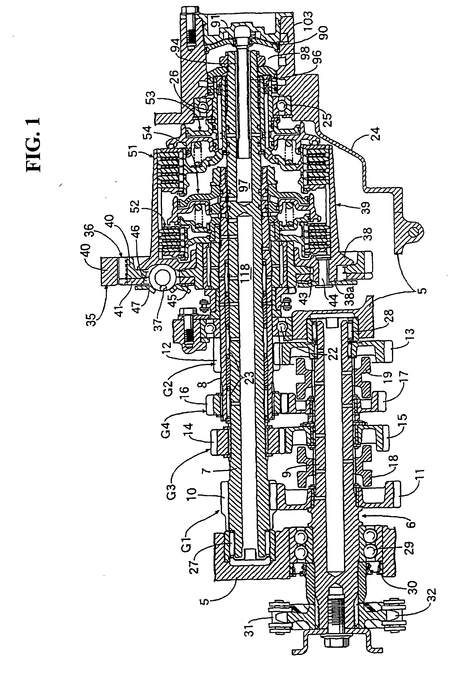
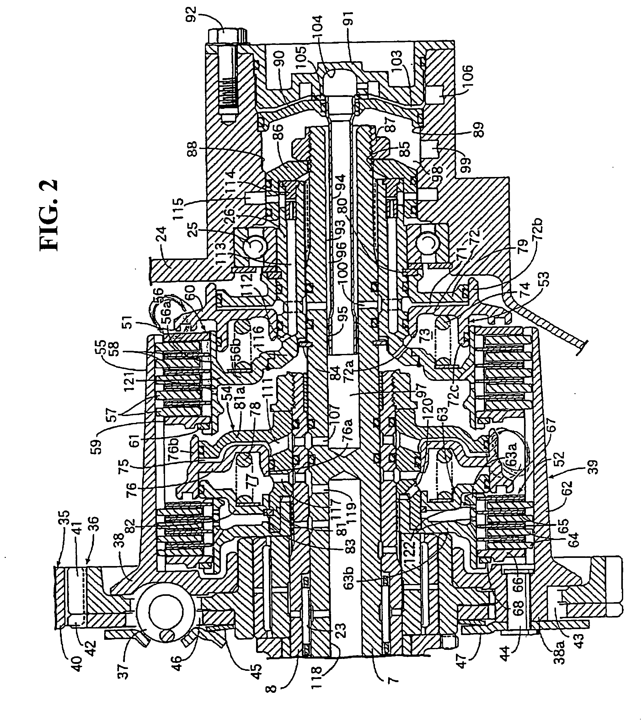
[0026]FIGS. 1 and 2 show the present invention, of which FIG. 1 is a longitudinal sectional view showing a part of an engine, and FIG. 2 is an enlarged main portion view of FIG. 1.

[0027] As illustrated in FIG. 1, for example, a crankcase 5 equipped to an engine mounted to a motorcycle accommodates a transmission 6 including a plurality of speeds of gear trains that can be selectively established, for example, first to fourth-speed gear trains G1, G2, G3, G4. The first-speed gear train G1 includes a first-speed driving gear 10 provided integrally with a first main shaft 7, and a first-speed driven gear 11 rotatably supported on a countershaft 9, which is parallel to the first main shaft 7, and brought into meshing engagement with the first-speed driving gear 10. The second-speed gear train G2 includes a second-speed driving gear 12 provided integrally with a second main shaft 8 that is coaxial with the first main shaft 7, and a second-speed driven gear 13 rotatably supported on the c...

second embodiment

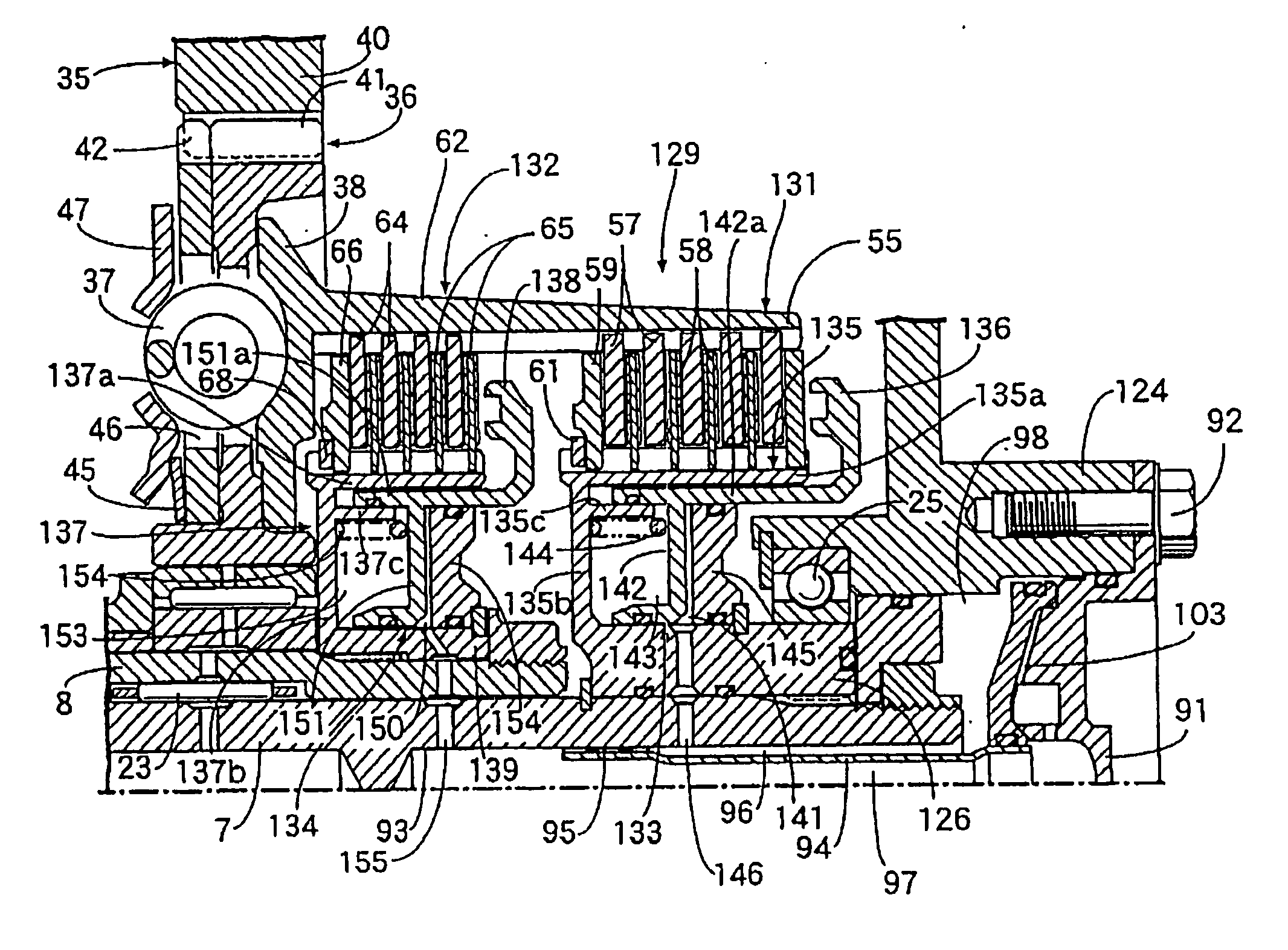
[0092] as described above, the first and second clutch disconnection / connection control mechanisms 133, 134 are arranged radially inwardly with respect to the first and second cylinder portions 135a, 137a of the first and second clutch inners 135, 137 respectively equipped to the first and second clutch actuating mechanisms 131, 132 arranged in parallel along the axes of the first and second main shafts 7, 8 that are coaxial. Accordingly, the first and second clutch disconnection / connection control mechanisms 133, 134 can be arranged by effectively utilizing the dead space between the first and second cylinder portions 135a, 137a, and the first and second main shafts 7, 8, whereby the twin-clutch device 129 can be made more compact with respect to the axial direction. In addition, the inertial mass of the twin-clutch device 129 can be reduced, thus allowing power from the drive source to be transmitted without causing a decrease in responsiveness.

[0093] Further, at the time of chan...


PUM


Abstract

To reduce the axial size of a twin-clutch device including first and second clutch actuating mechanisms arranged in parallel along the axes of first and second driven shafts that are coaxial. A first clutch disconnection / connection control mechanism is provided for switching disconnection / connection of the first clutch actuating mechanism. A second clutch disconnection / connection control mechanism is provided for switching disconnection / connection of the second clutch actuating mechanism. A second clutch disconnection / connection control mechanism is arranged between first and second clutch inners so that at least a part of the second clutch disconnection / connection control mechanism is accommodated in at least one of first and second cylinder portions.

Description

CROSS-REFERENCE TO RELATED APPLICATIONS [0001] The present application claims priority under 35 USC 119 to Japanese Patent Application No. 2005-377449 filed on Dec. 28, 2005 the entire contents of which are hereby incorporated by reference.BACKGROUND OF THE INVENTION [0002] 1. Field of the Invention [0003] The present invention relates to a twin-clutch device with a first clutch actuating mechanism including a first clutch outer that is continuous to a driving rotary member, and a first clutch inner having a first cylinder portion coupled to a first driven shaft in a relatively non-rotatable manner. A second clutch actuating mechanism includes a second clutch outer that is continuous to the driving rotary member. A second clutch inner is provided having a second cylinder portion coupled to a second driven shaft in a relatively non-rotatable manner. A first clutch disconnection / connection control mechanism is provided for exerting on the first clutch actuating mechanism a controlling...

Claims


Application Information

Patent Timeline
IPC IPC(8): F16D21/02
CPCF16D25/0638F16D25/10F16D2021/0661F16D21/06
Inventor IEDA, YOSHIHISATOMODA, AKIHIKOKANNO, YOSHIHISA
Owner HONDA MOTOR CO LTD
Why Eureka
Try Eureka