Transfer case with moving coil clutch actuator operator

a technology of moving coil and actuator, which is applied in the direction of magnetically actuated clutches, mechanical actuated clutches, transportation and packaging, etc., can solve the problems of operating systems that are not new, and achieve the effect of fast and more responsiveness and unprecedented responsiveness

Inactive Publication Date: 2007-06-28
DYMOS
View PDF15 Cites 8 Cited by
  • Summary
  • Abstract
  • Description
  • Claims
  • Application Information

AI Technical Summary

Benefits of technology

[0004] The present invention provides a new transfer case with a new and improved clutch actuator operator that is faster and more responsive than prior art clutch actuator operators. The operator is operably connected to an element of a clutch actuator that can be rotated, relative to another element of the clutch actuator, to effect or release compression in a transfer case disk pack. The operator comprises a stationary field assembly and a coil that is selectively energizable to cause relative linear movement between the field assembly and the coil. Such operators are not new and they are available commercially today. They are sometimes called moving coil actuators or voice coil actuators. What is new is the combination of a moving coil actuator and a ball ramp type transfer case clutch actuator to control the compression of a disk pack in a transfer case clutch. As used herein,

Problems solved by technology

Such operators are not new and the

Method used


Image

  • Transfer case with moving coil clutch actuator operator
  • Transfer case with moving coil clutch actuator operator
  • Transfer case with moving coil clutch actuator operator

Examples


Embodiment Construction

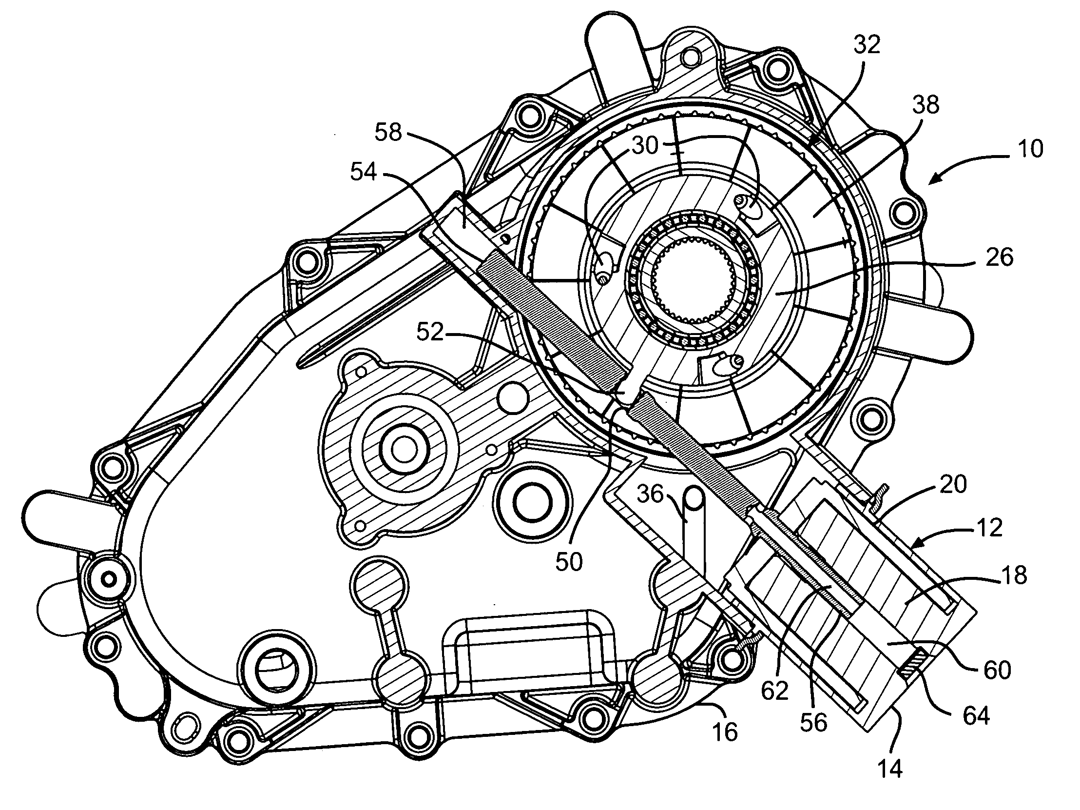
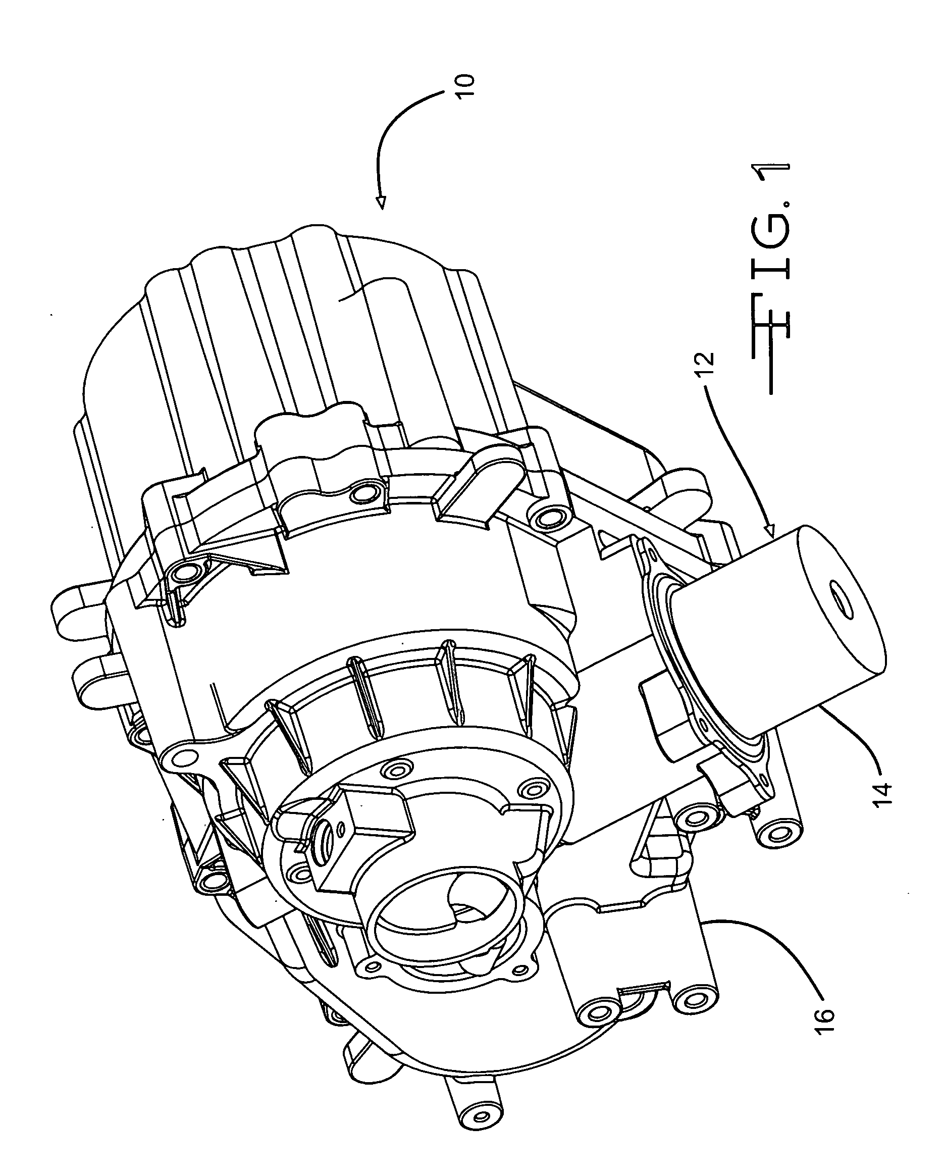
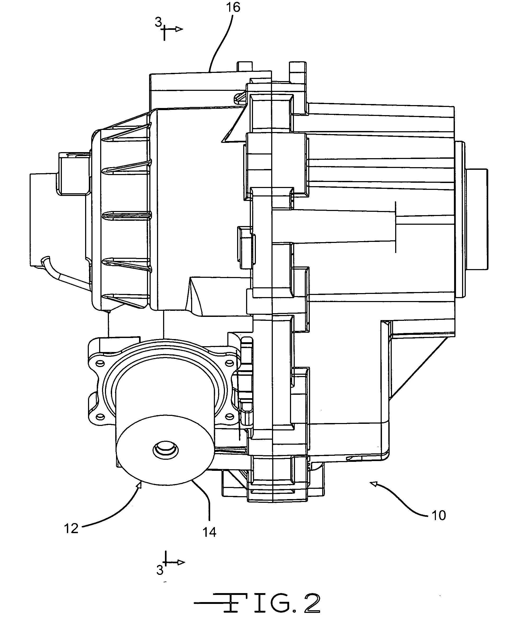
[0016] Referring now to the several drawing Figures in which like reference numerals have been used throughout to refer to like parts, a transfer case including a new actuator operator according to the present invention is indicated generally at 10. The transfer case 10 comprises an operator 12 with a housing 14 which is secured to a housing 16 of the transfer case 10. Inside of the housing 14, the operator 12 comprises a stationary field assembly 18 and a moving coil 20. The field assembly 18 includes a permanent magnet and the coil 20 is wound with wire so that, when it is energized with electric current, magnetic forces are generated in the moving coil 20 causing relative movement between the field assembly 18 and the moving coil 20. The moving coil 20 is movable by the generated forces between a first retracted position shown in FIG. 3 and FIG. 6, and a second, extended position shown in FIG. 4 and FIG. 7. A control rod 22 is secured to and supported in an end cap 24 that is par...


PUM


Abstract

A new transfer case with a new and improved clutch actuator and operator is disclosed. The operator is operably connected to a first element of a ball ramp type transfer case clutch actuator that can be rotated, relative to a second element of the clutch actuator, to effect or release compression in the disk pack of the transfer case clutch. The operator comprises a moving coil linear actuator having a stationary magnet and a coil that is mounted adjacent to the stationary magnet for reciprocating movement which is controlled by controlling the flow of current through the coil. Linear movement of the coil is translated into rotational movement of the first element of the clutch actuator by a connecting rod.

Description

FIELD OF THE INVENTION [0001] This invention relates to a power transfer mechanism of the type known as a transfer case in which torque is selectively transmitted through a friction engagement device. More particularly, the present invention relates to an operator for actuating a torque transfer case clutch disk pack compression mechanism, such as a ball ramp mechanism, that selectively causes engagement of the disk pack friction elements of the clutch for torque transmission. BACKGROUND OF THE INVENTION [0002] Automotive transfer cases are used in vehicles with four wheel drive to distribute torque to front and rear axles. Some transfer cases that do not provide full time four wheel drive are equipped with friction engagement devices that are selectively actuated to cause the transmission of torque to the axle(s) for the wheels that are not full time drive wheels. Typically, such friction engagement devices include disk packs that transmit torque when subjected to axial compression...

Claims


Application Information

Patent Timeline
IPC IPC(8): F16D27/115
CPCF16D27/004F16D27/115B60K17/344B60K17/34F16D45/00
Inventor BOWEN, THOMAS C.KIM, JIN S.
Owner DYMOS
Why Eureka
Try Eureka