Apparatus and method for inspecting areas surrounding nuclear boiling water reactor core and annulus regions

a technology for boiling water reactors and apparatus, applied in the direction of nuclear elements, television systems, greenhouse gas reduction, etc., can solve the problems and achieve the effect of shortening the duration of outages and saving costs

Inactive Publication Date: 2007-06-28
EXELON CORP
View PDF22 Cites 59 Cited by
  • Summary
  • Abstract
  • Description
  • Claims
  • Application Information

AI Technical Summary

Benefits of technology

[0013] The apparatus disclosed herein provides a remotely controlled inspection vehicle capable of movement on the reactor steam dam without using any additional platforms for the vehicle and without modifying the existing BWR structures. This eliminates the need to use the refueling bridge, the auxiliary bridge or other spe...

Problems solved by technology

The apparatus provides the ability to perform inspections independent of other critical pa...

Method used


Image

  • Apparatus and method for inspecting areas surrounding nuclear boiling water reactor core and annulus regions
  • Apparatus and method for inspecting areas surrounding nuclear boiling water reactor core and annulus regions
  • Apparatus and method for inspecting areas surrounding nuclear boiling water reactor core and annulus regions

Examples


Embodiment Construction

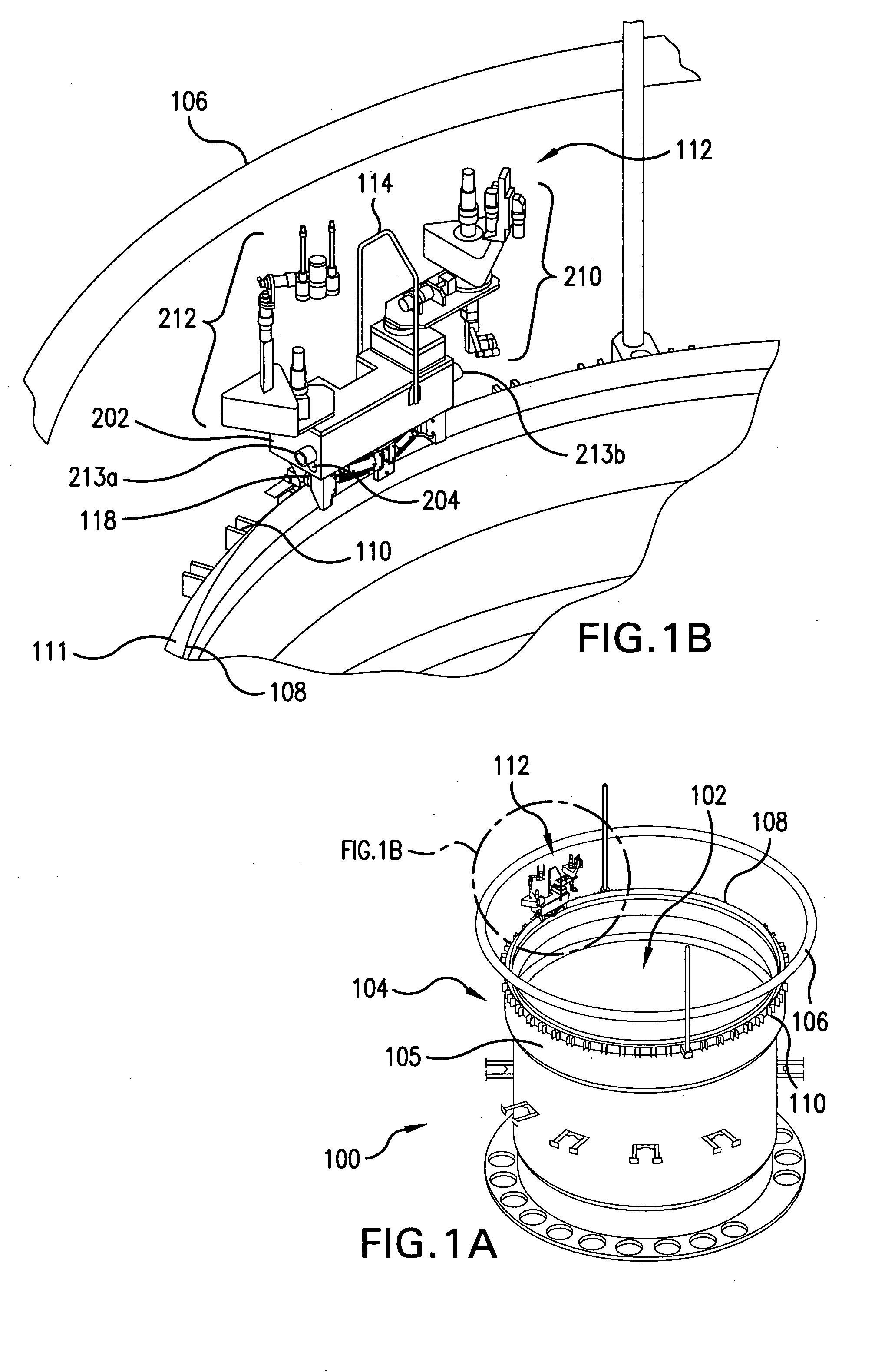
[0038]FIG. 1A is a perspective view of a BWR reactor vessel 100. The reactor vessel (also referred to as the Rx vessel) 100 includes a core region 102 and an annulus region 104, separated by a core shroud 105. Steam dam 108 is located above the core shroud 105, generally separating the core region 102 from the annulus region 104. The reactor vessel 100 also includes feedwater spargers and core spray piping 106, which provide coolant flow to the reactor vessel. The feedwater spargers and core spray piping 106 are located above the steam dam 108. A typical steam dam is ¼ of an inch thick and 4″ inches high. Slightly below the steam dam 108 are separator hold-down lugs 110. The hold-down lugs 110 are located adjacent to the core shroud flange 111. The hold-down lugs 110 hold down the steam separator (not shown).

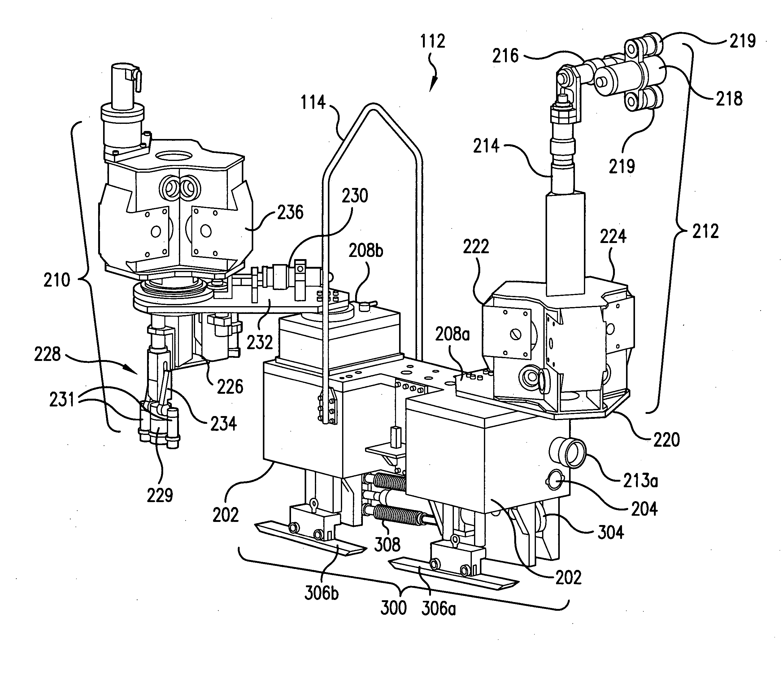
[0039]FIG. 1B is a perspective view of a selected area from FIG. 1A and shows a preferred embodiment of an inspection apparatus 112 in accordance with the present invention. FI...


PUM


Abstract

A remotely controlled apparatus (112) for inspecting the core (102) and annulus (104) areas of nuclear boiling water reactors (100) includes a circumferential drive mechanism for propelling the apparatus (112) on the steam dam (108) of the reactor (100). The inspection apparatus (112) uses a set of driver rollers (314) that grip the side of the steam dam (108) and provide propulsion for the apparatus. A pinch-roller assembly with high-tension springs (308) and pneumatic air cylinders (310) is utilized for removably securing a set of pinch rollers (312) to the side of the steam dam opposite the side of the driver rollers (314). A set of rollers (304) are adapted to rest on top of the steam dam (108), supporting the weight of the apparatus (112) and enabling the apparatus to move around the steam dam (108). Two positioning guide rails (306) aid in the balance of the apparatus (112), especially when it is stationary. The apparatus (112) has a watertight main body (202), which houses the electrical control wiring and circuitry. The main body (202) has a front camera (204) and a rear camera (205) used to direct the movements of the apparatus (112). The main body also has two turret-type telescoping mast assemblies (208) with telescoping masts 210 and 212, which are capable of extending at a selected distance above and below the main body (202). The mast assemblies 210 and 212 support inspection equipment such as radiation-shielded EVT-1-capable video cameras and radiation-tolerant fiberscopes. The apparatus (112) and its inspection tools are remotely controlled via control consoles with video monitors from a low-dose, non-contaminated enclosure located remotely from a boiling water reactor.

Description

FIELD OF THE INVENTION [0001] The present invention relates generally to an inspection tool and maintenance method for a nuclear power plant, and in particular, to a remotely operable inspection tool and method of using the same for inspecting boiling water reactor in-vessel, annulus and surrounding areas. BACKGROUND OF THE INVENTION [0002] Boiling water reactors (“BWRs”) typically utilize a jet pump system as a means of regulating reactor flow. In a common arrangement, twenty individual jet pumps, in two “loops” of ten each, are located in the annulus area just inside the reactor vessel invert. The annulus, the jet pumps and the core shroud are subject to scheduled and augmented inspections that may result in required maintenance or retrofit activities. [0003] Because water is used as a radiation shield in BWRs, much of the inspection activity occurs under water (see, e.g., U.S. Pat. No. 5,254,835 to Dalke et al., FIG. 1) (“the '835 patent”). Normally, Reactor Service Technicians (...

Claims


Application Information

Patent Timeline
IPC IPC(8): H04N7/18
CPCG21C17/01G21C17/013G21Y2002/304G21Y2002/40G21Y2004/30Y02E30/30
Inventor JUDGE, JOHN JOSEPH JR.BARON, MICHAEL JAMIE
Owner EXELON CORP
Why Eureka
Try Eureka