Optical apparatus

a technology of optical equipment and optical axis, which is applied in the field of optical equipment, can solve the problems of reducing the quality of finder images and picking up images, and the operator cannot disadvantageously check whether or not image stabilization is performed during aiming in the finder, and achieves the effect of saving power and good quality

Inactive Publication Date: 2007-06-28
CANON KK
View PDF2 Cites 41 Cited by
  • Summary
  • Abstract
  • Description
  • Claims
  • Application Information

AI Technical Summary

Benefits of technology

[0007] The present invention provides an optical apparatus capable of acquiring images with a good quality and saving power.

Problems solved by technology

However, in the optical apparatus disclosed in Japanese Patent No. 3189018, the operator cannot disadvantageously check whether or not the image stabilization is performed during aiming in the finder.
Thus, activating the image stabilization function only during image-pickup exposure results in a significant disadvantage.
In this case, the image stabilization optical element will become stable with the center thereof displaced from the optical axis of the primary optical system, inevitably resulting in reduced quality of finder images and picked-up images.

Method used


Image

  • Optical apparatus
  • Optical apparatus
  • Optical apparatus

Examples


first embodiment

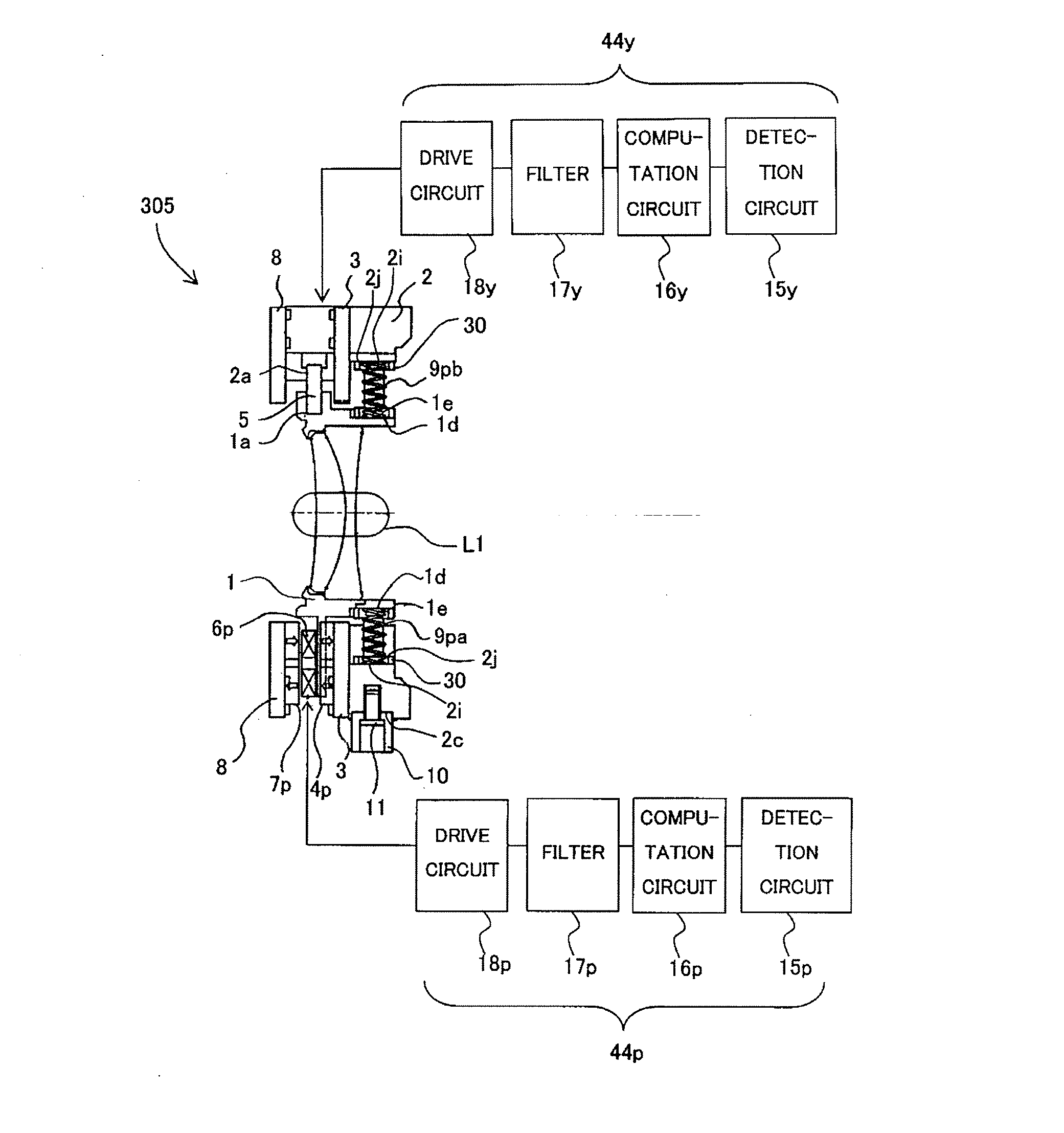
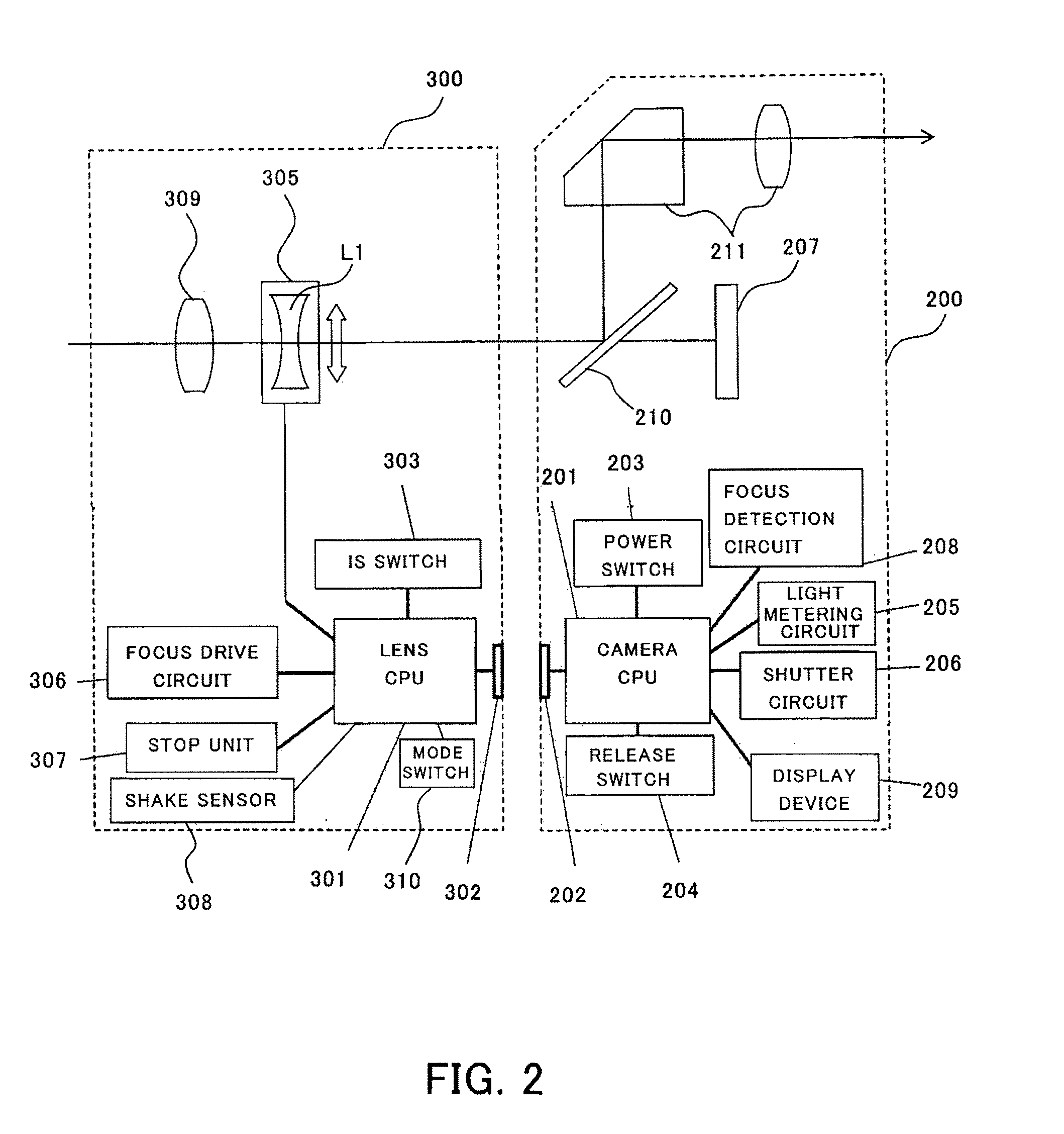
[0021]FIG. 2 shows the configuration of the image-pickup system that is the first embodiment of the present invention. The image-pickup system in this embodiment includes an interchangeable lens as an optical apparatus equipped with an image stabilization unit and a single-lens reflex digital camera as an image-pickup apparatus to and from which the interchangeable lens can be attached and detached. In FIG. 2, reference numeral 200 denotes the camera and reference numeral 300 denotes the interchangeable lens.

[0022] In the camera 200, reference numeral 211 denotes a finder optical system, and reference numeral 210 denotes a quick-return mirror for introducing light from the lens 300 to the finder optical system 211. Reference numeral 207 denotes an image-pickup element, such as a CCD sensor or a CMOS sensor, which photoelectrically converts a subject image formed by the lens 300.

[0023] Reference numeral 201 denotes a camera CPU as a camera-side microcomputer that controls the opera...

second embodiment

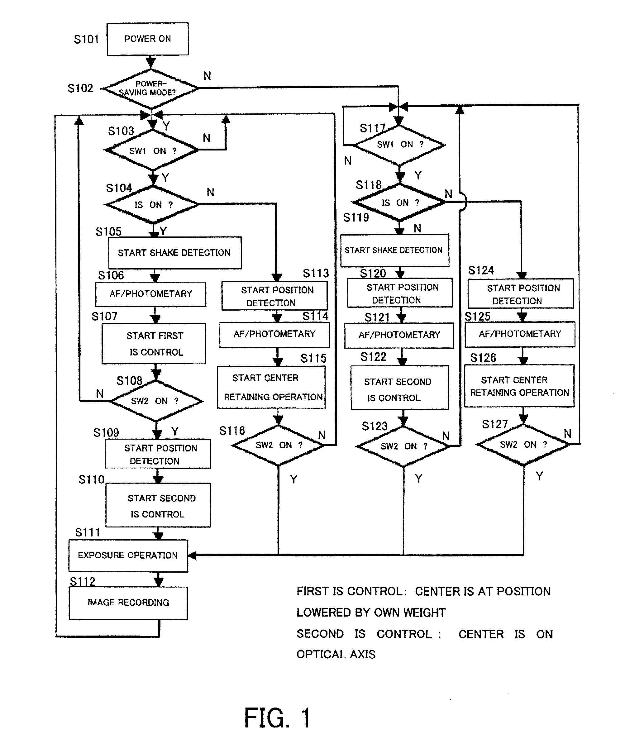
[0110] In the first embodiment described above, the description has been made of a case where in the power saving mode, when the SW1 is ON, the power-saving image stabilization operation is performed with respect to the first position as the center of movement, while when the SW2 is ON, the operation is switched to the image stabilization operation for acquiring high-quality images that is performed with respect to the second position as the center of movement. However, when an image quality switching capability that allows the user to switch, for example, between a low-quality image-pickup mode and a high-quality (standard) image-pickup mode, is equipped and the low-quality image-pickup mode is selected, the image stabilization operation may be performed with respect to the first position as the center of movement not only when the SW1 is ON, but also when the SW2 is ON (during image-pickup). In this way, further power saving can be achieved.

[0111] The image-pickup operation in th...


PUM


Abstract

An optical apparatus is disclosed which is capable of acquiring images with a good quality and saving power. The optical apparatus comprises a movable unit which is supported by an elastic member and movable for image stabilization and a controller. The controller performs a first control operation which controls drive of the movable unit with respect to a first position as the center of movement where the weight of the movable unit itself and a supporting force of the elastic member are balanced, and a second control operation which controls drive of the movable unit with respect to a second position as the center of movement, the second position being shifted from the first position in the direction opposite to the gravity direction toward the optical axis of an optical system that forms an object image.

Description

BACKGROUND OF THE INVENTION [0001] The present invention relates to an optical apparatus, such as an interchangeable lens and an image-pickup apparatus, equipped with an image stabilization (image-shake correction) function, and particularly to an optical apparatus that drives a movable unit, such as a lens and an image-pickup element, for image stabilization. [0002] There have been disclosed quite a few conventional optical apparatuses equipped with an image stabilization function in which a shake sensor, such as an angular velocity sensor, detects shake caused by hand shake or the like and based on the detection result, an actuator displaces an image stabilization optical element to cancel image shake. [0003] In such an optical apparatus equipped with an image stabilization function, Japanese Patent No. 3189018 has disclosed an approach to reduce power consumption. In this approach, the image stabilization function is activated only during image-pickup exposure operation but is no...

Claims


Application Information

Patent Timeline
Patent Type & Authority Applications(United States)
IPC IPC(8): G02B27/64
CPCG03B5/00G03B2205/0007G03B2217/005G03B2205/0053
Inventor AKADA, HIROSHIISHIKAWA, MASANORISUGITA, JUNINOUE, KATSUHIROITO, SAWAKO
Owner CANON KK
Why Eureka
Try Eureka