Lens barrel and image pickup apparatus

Inactive Publication Date: 2007-06-28
SONY CORP
View PDF0 Cites 0 Cited by
  • Summary
  • Abstract
  • Description
  • Claims
  • Application Information

AI Technical Summary

Benefits of technology

[0015] Accordingly, the detection signal outputted from the magnetic resistance sensor apparatus has the best quality, and this is advantageous in accurate position detection of the lens moving frame and hence in acquisition of a clear image.
[0016] Further, the magnetic resistance sensor apparatus has a simple configuration in that it includes a single screw and a plurality

Problems solved by technology

However, in the lens barrel described above, since the magnetic resistance sensor device is rocked for adjustment of the gap as described above, the sensing face is liable to be inclined with respect to the magnetized face.
Therefore, it is difficult to keep the state wherein the sensing face extends in parallel to the magnetized face, and consequently, it is difficult to assure the quality of the detection sign

Method used


Image

  • Lens barrel and image pickup apparatus
  • Lens barrel and image pickup apparatus
  • Lens barrel and image pickup apparatus

Examples


first embodiment

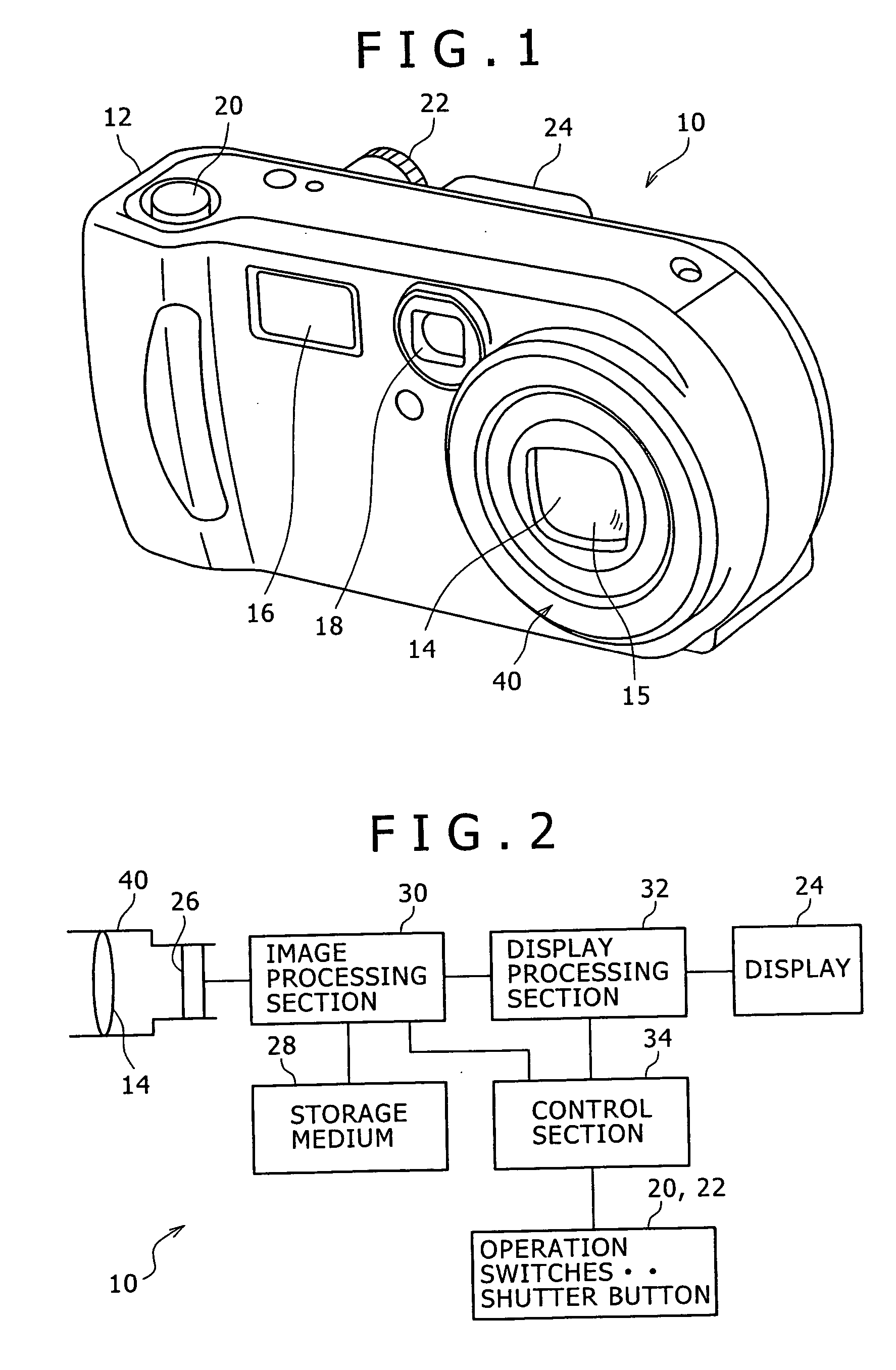
[0028] First, a first preferred embodiment of the present invention is described. FIG. 1 is a perspective view of an image pickup apparatus according to the first embodiment, and FIG. 2 is a block diagram showing a configuration of the image pickup apparatus.

[0029] Referring first to FIG. 1, the image pickup apparatus 10 of the present embodiment is formed as a digital still camera and includes a casing 12 which forms a jacket.

[0030] A lens barrel 40 is provided at a portion of a front face of the casing 12 rather near to the right side in FIG. 1. The lens barrel 40 accommodates and holds an optical system 14 therein.

[0031] An image pickup device 26 (refer to FIG. 2) is provided at a rear portion of the lens barrel 40, and the optical system 14 provided in the lens barrel 40 introduces an image of an image pickup subject to the image pickup device 26. An objective lens 15 forms part of the optical system 14 and is provided at a front end of the lens barrel 40.

[0032] A flash sect...

second embodiment

[0102] Now, a second preferred embodiment of the present invention is described.

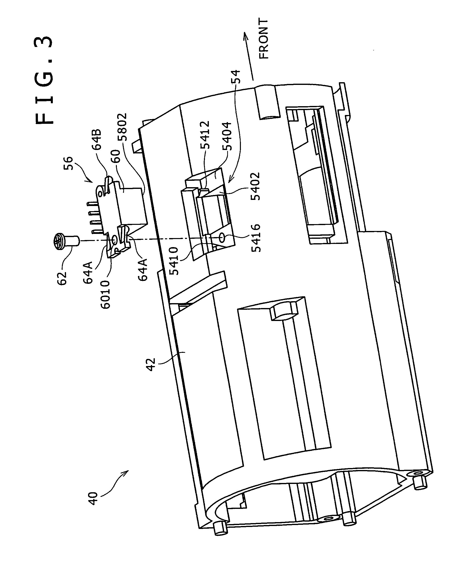
[0103]FIG. 8 is a perspective view of a lens barrel 40 according to the second embodiment of the present invention.

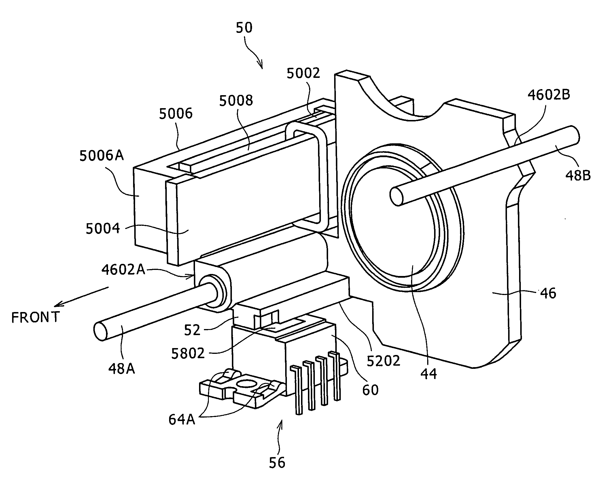
[0104] The second embodiment is a modification to but is different from the first embodiment described hereinabove in that the magnetic resistance sensor apparatus 56 is attached to the attaching portion 54 in a state wherein the sensing face 5802 is rotated by 90 degrees around an axial line which extends perpendicularly to the magnetized face 5202 and passes the magnetized face 5202.

[0105] In particular, in the second embodiment, the sensor holding portion 6002 (the body 60) has a width along the direction in which the lens moving frame 46 is moved back and forth linearly. Further, the screw insertion hole 6010, (that is, the location of the body 60 at which the single screw 62 is fitted), is positioned on the center axis C2 of the sensor holding portion 6002 (the body 60) which passes ...

third embodiment

[0108] Now, a third preferred embodiment of the present invention is described.

[0109]FIG. 9 is a perspective view of a magnetic resistance sensor apparatus 56 according to the third embodiment of the present invention.

[0110] The third embodiment is a modification to but is different from the first embodiment described hereinabove in the location of guide holes 6414 and the number and the location of the resilient pieces 64.

[0111] Referring to FIG. 9, the sensor holding portion 6002 (the body 60) has a width in a direction perpendicular to the direction in which the lens moving frame 46 is moved back and forth linearly similarly as in the first embodiment.

[0112] The screw insertion hole 6010, (that is, the location of the body 60 at which the single screw 62 is fitted), the guide groove 6012 and the guide hole 6414 are positioned on the center axis C2 of the sensor holding portion 6002 (the body 60) which passes the center of the width and extends in the direction in which the le...


PUM


Abstract

A lens barrel includes a lens moving frame configured to hold an image pickup lens; a barrel member configured to support the lens moving frame for back and forth linear movement along the direction of an optical axis of the image pickup lens; the lens moving frame having a magnetized face magnetized alternately with N poles and S poles along the direction of the back and forth linear movement; and a magnetic resistance sensor apparatus. The magnetic resistance sensor apparatus has a magnetic resistance sensor, a body, a single screw, and a plurality of resilient pieces. The resilient pieces is formed such that, in a state wherein the resilient pieces are resiliently deformed all by the same amount, the sum of moments by the resilient pieces which act upon the location of the body at which the screw is fitted is zero.

Description

CROSS REFERENCES TO RELATED APPLICATIONS [0001] The present invention contains subject matter related to Japanese Patent Application JP 2005-314555 filed with the Japanese Patent Office on Oct. 28, 2005, the entire contents of which being incorporated herein by reference. BACKGROUND OF THE INVENTION [0002] 1. Field of the Invention [0003] This invention relates to a lens barrel and an image pickup apparatus. [0004] 2. Description of the Related Art [0005] An image pickup apparatus such as a digital still camera or a digital video camera has a lens barrel provided therein. [0006] A lens barrel of the type is known which includes a lens moving frame for holding an image pickup lens thereon and a barrel member for supporting the lens moving frame for back and forth linear movement along the direction of an optical axis of the image pickup lens. The lens moving frame is moved by a zooming action or a focusing action. [0007] In order to control the movement of the lens moving frame, it i...

Claims


Application Information

Patent Timeline
IPC IPC(8): G02B7/02
CPCG02B7/102H04N5/2254H04N23/55G02B7/08G03B17/04G02B7/026
Inventor HATTORI, KAZUHIRO
Owner SONY CORP
Why Eureka
Try Eureka