A servo tool magazine based on machine vision tool arm positioning and its tool change control method

A technology of machine vision and tool magazine, applied in positioning devices, manufacturing tools, metal processing machinery parts, etc., to achieve stable work, ensure replacement accuracy, and avoid narrow applicability

Active Publication Date: 2021-11-05
OKADA SEIKI DANYANG CO LTD
View PDF3 Cites 0 Cited by
  • Summary
  • Abstract
  • Description
  • Claims
  • Application Information

AI Technical Summary

Problems solved by technology

[0007] In order to solve the problem of precise positioning of the knife arm rotation in the prior art, the present invention designs a servo tool magazine and its tool change control method based on machine vision knife arm positioning. We only need to consider the precise positioning of the knife arm. Precise operation of knife and knife loading

Method used


Image

  • A servo tool magazine based on machine vision tool arm positioning and its tool change control method
  • A servo tool magazine based on machine vision tool arm positioning and its tool change control method
  • A servo tool magazine based on machine vision tool arm positioning and its tool change control method

Examples


Embodiment 1

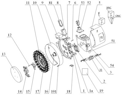
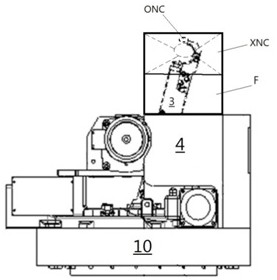
[0071] Such as Figure 1-4 As shown, a servo tool magazine includes: tool magazine body 1, cam mechanism 2, knife arm structure 3,

[0072] ATC shield 4, ATC tool changing mechanism 5, ATC reducer 52, ATC servo motor 53, cam positioning sensor 6, tool magazine reducer fixed

[0073] Seat 7, tool magazine reducer 8, tool magazine servo motor 81, control box 9, tool magazine rear cover 10, disc cutter head unit 11, origin sensor 12, tool magazine front cover 13, knife reversing cylinder group 14. Knife reversing micro switch 15, cutter head spindle 16, knife holder structure 17, reversing knife positioning seat 18, servo driver 19;

[0074] Wherein, the cam mechanism 2 is arranged at the rear portion of the tool magazine body 1, and the cam positioning sensor 6 is arranged at the rear portion of the tool magazine body 1 and is positioned above the cam mechanism 2. unit 11 transmission connection,

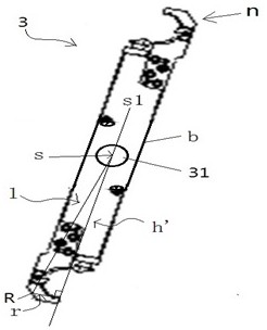
[0075] The knife arm structure 3 has a drive shaft sleeve 31 that is sheathed ...

Embodiment 2

[0089] Such as Figure 4 As shown, the present invention also provides a tool change control method for a servo tool magazine, comprising the following steps:

[0090] (1) Calibrate the position of the origin of the knife arm structure 3: set a point in the middle of the handle part n as the reference point R, connect the reference point R and the rotational symmetry point s, and pass the reference point R to make the symmetry The vertical line of the axis s1 is used to obtain the reference vertical segment r between the vertical foot and the reference point; start the ATC servo motor 53 at the rated speed to drive the knife arm structure 3 to rotate, when the origin sensor 12 detects that the knife arm structure 3 returns to the initial position , the ATC servo motor continues to drive the knife arm 3 structure to rotate for 30s at the lowest speed of 1r / min, then stops the ATC servo motor, and then reverses the ATC servo motor 53 at the lowest speed until the origin sensor 1...

Embodiment 3

[0117] In the step S1-S3.2 in the embodiment 2, the corresponding angle difference is obtained every time the difference is obtained, and the actual angle difference measured by the actual angle monitoring encoder 54 of the knife arm is also used as an average value, and the average value is used as a new value. The comparison object for adjusting the position of the knife arm.


PUM


Abstract

The invention relates to a servo tool magazine and its tool change control method, characterized in that: the servo tool magazine includes: a tool magazine body, a cam mechanism, a knife arm structure, an ATC shield, an ATC tool change mechanism, an ATC reducer, an ATC servo Motor, cam positioning sensor, fixed seat of tool magazine reducer, tool magazine reducer, tool magazine servo motor, control box, tool magazine rear cover, disc cutter head unit, origin sensor, tool magazine front cover, reversing knife Cylinder group, knife reversing micro switch, cutterhead mandrel, knife sleeve structure, reversing knife positioning seat, servo driver, high-definition pinhole camera and X-ray pinhole camera are installed at the rear of the ATC shield for detecting the Optical images and X-ray images of the gripper are taken. The machine vision technology that compares the optical image and X-ray image of multiple position detection devices with the standard image is accurately detected to ensure the accuracy of tool replacement. At the same time, a neural network model is established to control the operation of the ATC servo motor in real time through image recognition, making the position control of the knife arm more intelligent and precise.

Description

technical field [0001] The invention relates to a tool magazine structure and a control method thereof, in particular to a servo tool magazine based on machine vision knife arm positioning and a tool change control method thereof. Background technique [0002] In the existing precision mechanical forming process, the processing of a single part often involves various processing technologies such as boring, milling, cutting, cutting, drilling, etc., and a single type of tool often cannot meet the needs of multiple processing types. , so in the process of processing a single part, it is often necessary to make timely replacement and adjustment of the processed tool. The existing technology generally includes two methods of manual replacement and mechanical replacement. For the manual replacement method, although the replacement effect is accurate, The resulting processing error is small, but the replacement is time-consuming and labor-intensive, and manual position detection i...

Claims


Application Information

Patent Timeline
Patent Type & Authority Patents(China)
IPC IPC(8): B23Q3/157B23Q3/16
CPCB23Q3/16B23Q3/15722
Inventor 陈亮朱建国
Owner OKADA SEIKI DANYANG CO LTD
Why Eureka
Try Eureka