Super slim LCD backlight device using uniforming chamber

a backlight device and uniforming chamber technology, applied in the direction of planar/plate-like light guides, lighting and heating apparatuses, instruments, etc., can solve the problems of ineffective cost and yield improvement of light guide plates, difficulty in fabricating large-size light guide plates, and lack of side-edge typed techniques, etc., to achieve highly uniform planar light without sacrificing cost, heat dissipation and power consumption. , the effect of high light uniformity

Inactive Publication Date: 2007-06-28
DYNASCAN TECH
View PDF9 Cites 28 Cited by
  • Summary
  • Abstract
  • Description
  • Claims
  • Application Information

AI Technical Summary

Benefits of technology

[0010] Accordingly, the major objective of the present invention is to provide a LED-based backlight device which, on one hand, could shrink the thickness to the minimum without sacrificing cost, heat dissipation, and power consumption and, on the other hand, could deliver a highly uniform planar light regardless of the length of its usage period, the differences of LEDs' hues and brightness, and whether some LEDs are failed.

Problems solved by technology

The aforementioned side-edge typed technique has quite a few disadvantages, especially for large-size LCDs.
For example, large-size light guide plates are difficult to fabricate by molding; the cost and yield of the light guide plate cannot be improved effectively.
In addition, the area of the light entering plane of the light guide plate is too small compared to the LCD's panel area; a uniform planar light is difficult to achieve.
LEDs have gradually become the mainstream light source for backlight devices as, on one hand, the mercury vapor contained in the CCFL tubes presents an environmental hazard during fabrication and recycling as well.
The major drawback for LED-based, direct typed backlight devices is that, as individual LEDs' hues and brightness could not be exactly identical and their responses to environmental factors such as temperature are also different, the differences between their hues and brightness deteriorate as their usage time extends.
Even though the diffusion plate could balance out such variations and achieve a uniform planar light, its uniforming effect would be inadequate when one or more LEDs differ from the others up to a certain degree or when they are completely broken down.
If the spacing (d′) is reduced so as to shrink the thickness (D′), this would have a negative impact on the cost, power consumption, and heat dissipation to the backlight device as there will be a larger number of LEDs arranged densely.
Another drawback of LED-based direct typed backlight devices, therefore, is that the sensors are usually configured at the sides, instead of directly on the paths of the output lights, to avoid blocking the output lights.
As such, due to that these sensors are away from the output lights' paths and due to the non-uniformity of output lights, they do not accurately reflect the characteristics of the output lights.

Method used


Image

  • Super slim LCD backlight device using uniforming chamber
  • Super slim LCD backlight device using uniforming chamber
  • Super slim LCD backlight device using uniforming chamber

Examples


first embodiment

[0026]FIG. 2a is a schematic diagram showing a backlight device according to the present invention. As illustrated, the backlight device at least contains multiple LEDs 10 as a light source and a uniforming chamber 20 positioned between the LEDs 10 and the LCD panel (not shown). Please note that the LEDs 10 could be all white-light LEDs, or could contain red-, green-, and blue-light LEDs, or could be partly white-light LEDs and partly red-, green-, and blue-light LEDs, or any appropriate combination of colored LEDs. The LEDs 10 could be arranged in an array with regular spacing, or the LEDs 10 could be grouped (e.g., one red-light, one blue-light, and two green-light LEDs a group) and the groups are arranged in an array with regular spacing, or the LEDs 10 could be arranged in any appropriate manner. In other words, the present invention does not require the LEDs 10 to have any specific color combination or location arrangement. As to the total number of LEDs 10, it is dependent on ...

second embodiment

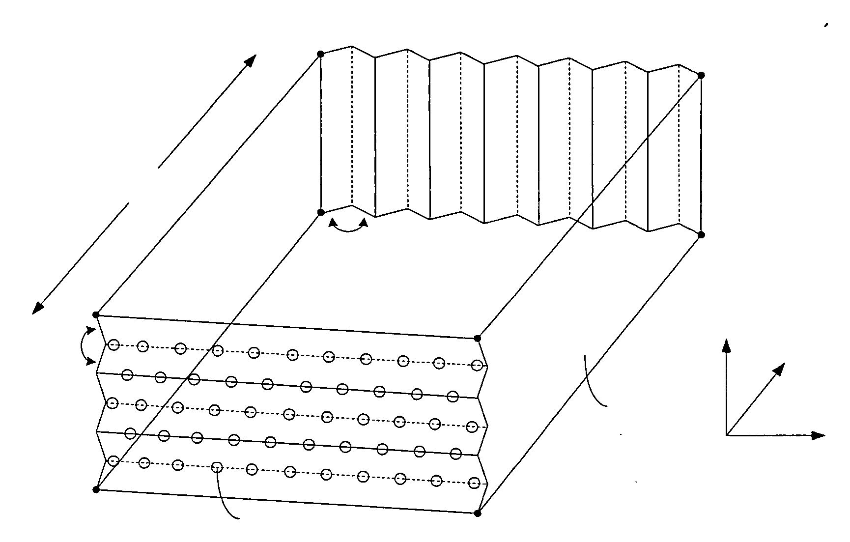
[0039]FIG. 3a is a schematic diagram showing a backlight device according to the present invention. The present embodiment is identical to the previous embodiment with only the following differences: (1) The light emitting plane (i.e., the A-B-C-D plane) contains a series of rectangular planes aligned in parallel with the adjacent planes' sides joined together with an included angle θ1 between 180° and 90° so that wave-like crests and troughs are formed along the X axis; and (2) The light entering plane (i.e., the E-F-G-H plane) contains a series of rectangular planes aligned in parallel with the adjacent planes' sides joined together with an included angle θ2 between 180° and 90° so that wave-like crests and troughs are formed along the Y axis. Please note that, when θ1=θ2=180°, the present embodiment is identical to the previous embodiment.

[0040]FIG. 3b is a schematic diagram showing the operation of the uniforming chamber of the backlight device of FIG. 3a, which is a top view al...


PUM


Abstract

A backlight device for LCD displays is disclosed herein. The backlight device contains multiple LEDs as light source and a uniforming chamber positioned between the LEDs and the LCD panel. Lights emitted from the LEDs undergo multiple times of total reflection by the inner walls of the uniforming chamber to produce a highly uniform planar light, regardless of the length of their usage period, the differences of LEDs' hues and brightness, and whether some LEDs are failed. The backlight device does not require the diffusion plates and prism plates, which not only reduces cost but also avoids the luminous flux loss. Also, the backlight device could achieve the slimmest thickness without sacrificing cost, heat dissipation, and power consumption.

Description

BACKGROUND OF THE INVENTION [0001] 1. Field of the Invention [0002] The present invention generally relates to backlight devices for liquid crystal displays, and more particularly to backlight devices using light emitting diodes as light source. [0003] 2. The Prior Arts [0004] Conventionally, backlight devices or backlight modules for liquid crystal displays (LCDs) or LCD TVs usually utilize a side-edge typed technique with cold cathode fluorescent lamps (CCFLs) or light emitting diodes (LEDs) as light source. Lights emitted from the light source are directed into a side of the light guide plate of a backlight device. The lights are then redirected to shoot out of a light emitting plane of the light guide plate by the diffusion dots configured on a surface of the light guide plate. As the lights pass through the light guide plate with a very significant emitting angle, diffusion plate and prism plate are employed for both uniforming and redirecting purposes so as to improve the unif...

Claims


Application Information

Patent Timeline
Patent Type & Authority Applications(United States)
IPC IPC(8): F21V13/04F21V7/05
CPCG02B6/0011G02B6/0016G02B6/0038G02B6/0068G02B6/0096
Inventor WANG, TSUN-I
Owner DYNASCAN TECH
Why Eureka
Try Eureka