Liquid crystal display device and projector

a liquid crystal display and projector technology, applied in liquid crystal compositions, instruments, chemistry apparatus and processes, etc., can solve the problems of difficult optical compensation of oblique incident light beam, high cost of sapphire, repeating complex calculations, etc., and achieve good viewing angle characteristics and high quality

Inactive Publication Date: 2009-02-26
SEIKO EPSON CORP
View PDF3 Cites 1 Cited by
  • Summary
  • Abstract
  • Description
  • Claims
  • Application Information

AI Technical Summary

Benefits of technology

[0013]Since the projector includes the above-mentioned liquid crystal display device and can be designed using a simple method, it is possible to provide a projector that can project an image with high quality by the use of a liquid crystal display device having a relatively good viewing angle characteristic.

Problems solved by technology

As a result, it is necessary to consider many parameters to determine the thickness of the optical compensating element and it is also necessary to repeat complex calculations even with a slight change in design.
When a sapphire plate is sued as the optical compensating element, the difference in refractive index from the quartz glass constituting the liquid crystal panel is greater than that of a quartz plate, thereby making it difficult to optically compensate for an obliquely incident light beam.
Sapphire is more expensive than materials such as quartz, thereby increasing the cost for the optical compensating element.
In addition, sapphire has hardness higher than the material such as quartz and it is difficult to process sapphire.

Method used


Image

  • Liquid crystal display device and projector
  • Liquid crystal display device and projector
  • Liquid crystal display device and projector

Examples


first embodiment

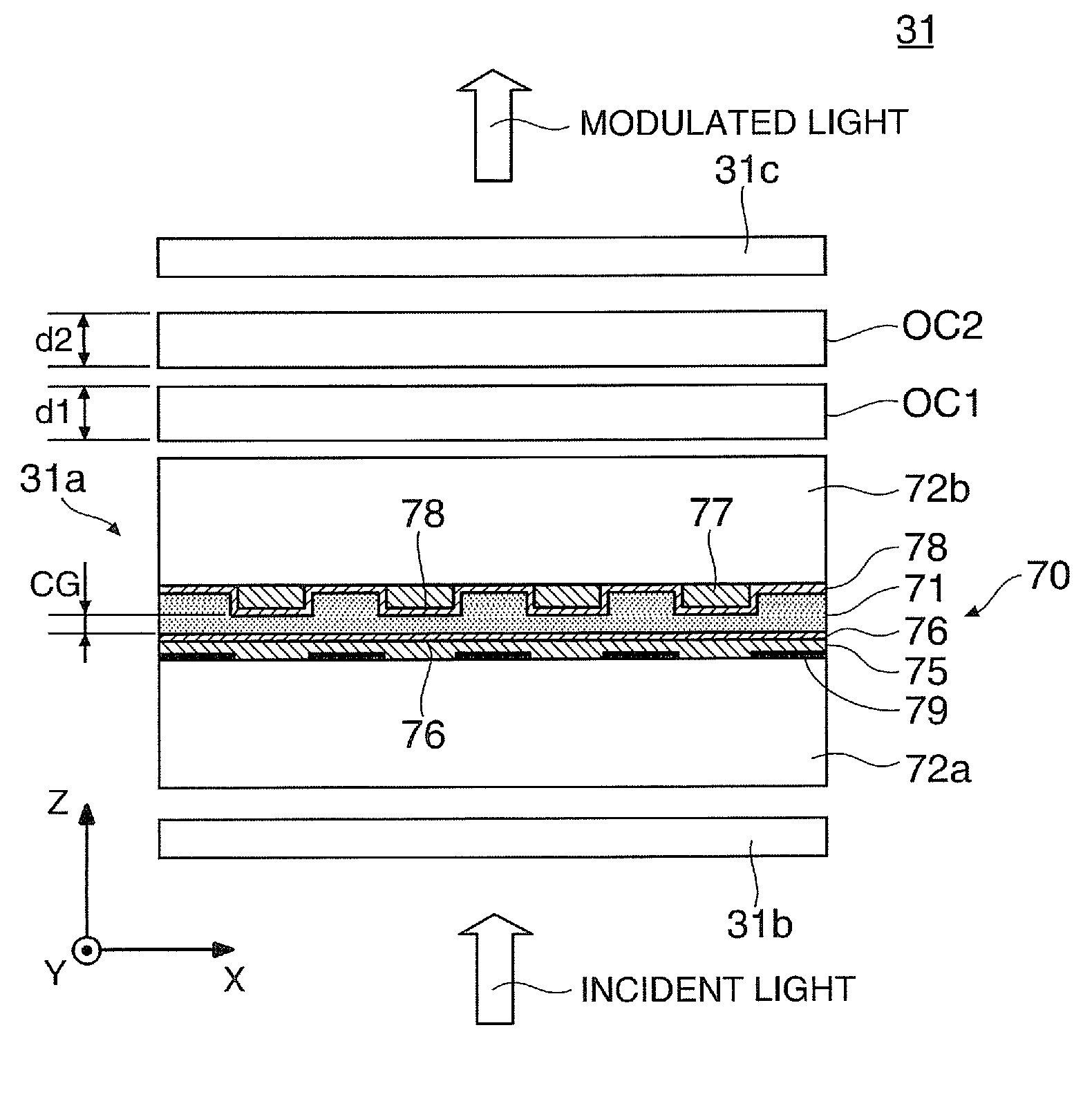
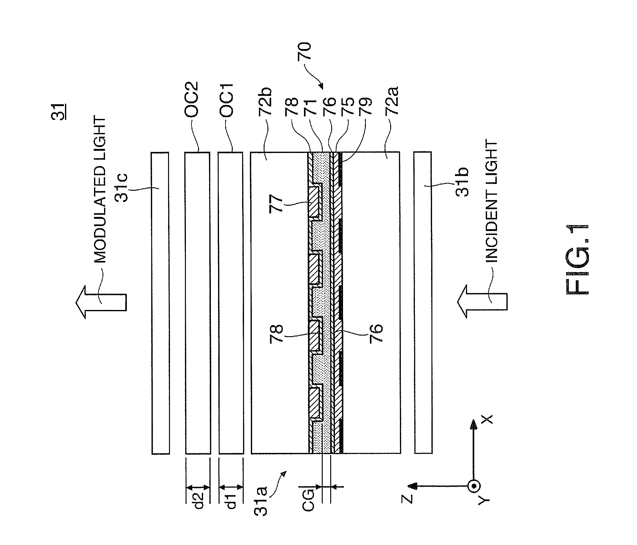
[0024]FIG. 1 is an enlarged sectional view illustrating a structure of a liquid crystal light valve (light modulator) as a liquid crystal display device according to a first embodiment of the invention.

[0025]In a liquid crystal light valve 31 shown in the drawing, a first polarizing filter 31b which is an incidence-side polarizing element and a second polarizing filter 31c which is an emission-side polarizing element constitute, for example, a cross Nicol. A polarization modulating unit 31a interposed between the first and second polarizing filters 31b and 31c is a liquid crystal panel changing the polarization direction of incident light in the unit of pixels in accordance with an input signal.

[0026]The polarization modulating unit 31a includes a liquid crystal cell 70 having a first transparent substrate 72a close to the incidence side and a second transparent substrate 72b close to the emission side, which a liquid crystal layer 71 having liquid crystal operating in a twisted nem...

second embodiment

[0059]FIG. 7 is a diagram illustrating a configuration of an optical system of a projector equipped with the liquid crystal light valve 31 shown in FIG. 1.

[0060]The projector 10 includes a light source unit 21 generating a source light beam, a color-separating optical system 23 separating the source light beam from the light source unit 21 into three-color beams of red, green, and blue, a light modulating unit 25 receiving the color beams emitted from the color-separating optical system 23, a cross dichroic prism 27 synthesizing the color beams from the light modulating unit 25, and a projection lens 29 as a projection optical system projecting an image beam from the cross dichroic prism 27 onto a screen (not shown). The light source unit 21, the color-separating optical system 23, the light modulating unit 25, and the cross dichroic prism 27 constitute an image forming apparatus forming an image beam to be projected onto the screen.

[0061]In the projector 10, the light source unit 2...


PUM

PropertyMeasurementUnit
thicknessaaaaaaaaaa
thicknessaaaaaaaaaa
thicknessaaaaaaaaaa

Abstract

A liquid crystal display device includes: a liquid crystal cell including liquid crystal operating in a twisted nematic mode; a first quartz plate optically compensating for the liquid crystal cell; a second quartz plate optically compensating for the liquid crystal cell; and a pair of polarizing elements disposed with the liquid crystal cell, the first quartz plate, and the second quartz plate interposed therebetween. Here, the thickness d [μm] of the first and second quartz plates, the polar angle θ [°] of the optical axis of the first and second quartz plates, and the cell gap CG [μm] of the liquid crystal cell satisfy the following conditional expressions:
0.7(16 cos2 θ−23.6 cos θ+14.6)(1+0.32(CG−3.0))<d   (1)
d<1.3(16 cos2 θ−23.6 cos θ+14.6))(1+0.32(CG−3.0))   (2).

Description

BACKGROUND[0001]1. Technical Field[0002]The present invention relates to a liquid crystal display device for forming an image and a projector having the liquid crystal display device.[0003]2. Related Art[0004]In the past, liquid crystal projectors using a twisted-nematic liquid crystal panel were known in which two sheets of optical compensating elements formed of a sapphire plate having an optical axis parallel to a rubbing direction and tilted by a predetermined angle about an incidence surface are disposed between a liquid crystal panel and an incidence polarizing plate or an emission polarizing plate (see JP-A-2004-198650).[0005]However, in order to determine the thickness of the optical compensating elements in the above-mentioned liquid crystal panel, it is necessary to know information such as how the liquid crystal molecules rise upright in an actual black display, what alignment distribution the light has, and what the polar angle of the optical axis of the optical compensa...

Claims


Application Information

Patent Timeline
Patent Type & Authority Applications(United States)
IPC IPC(8): G02F1/1335
CPCG02B27/286G02F1/1396G02F1/13363
Inventor ENDO, TAKASHIKARASAWA, JOJI
Owner SEIKO EPSON CORP
Why Eureka
Try Eureka