
Automotive AC generator designed to establish shaft-to-shaft connection with engine

a technology of ac generator and engine, which is applied in the direction of magnetic circuit rotating parts, couplings, magnetic circuit shape/form/construction, etc., can solve the problems of increasing the production cost of bearings, increasing the difficulty of machining bearings, and wear of bearings within the housing of alternators, so as to avoid seizing or creeping bearings

Inactive Publication Date: 2007-08-23
DENSO CORP
View PDF11 Cites 2 Cited by
  • Summary
  • Abstract
  • Description
  • Claims
  • Application Information

AI Technical Summary

Benefits of technology

[0010]It is another object of the invention to provide an improved structure of an automotive AC generator designed to minimize the seizing or creep of bearings without sacrificing production costs and assembling workability thereof.
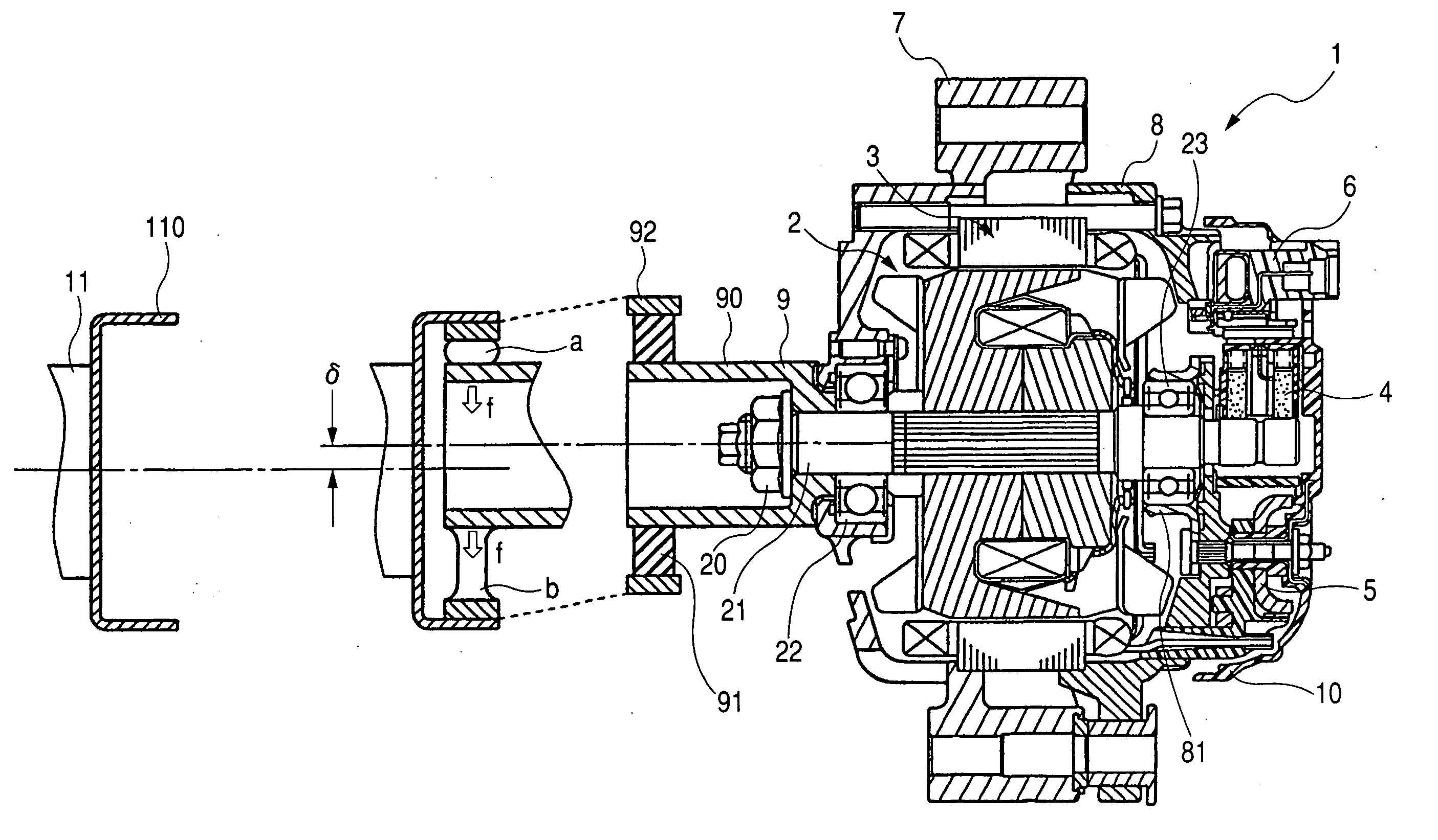
[0014]Specifically, the eccentricity between the generator connector and the motor connector results in the radial load acting on the bearing in one direction so as to keep a total load on the bearing greater than zero (0) at all the time. This avoids the seizing or creeping of the bearing.

Problems solved by technology

This may result in seizing of the bearings arising from a lack of lubricant caused by the slip of rolling elements on rolling contact surfaces of races or creep between a bearing holder and the outer race of the bearing, thus leading to the wear of the bearing within a housing of the alternator.
The former structure requires the need for controlling the configuration of the inner and outer races, that is, the size of the small gaps accurately, thus resulting in an increased difficulty in machining the bearing and an increased production cost of the bearings.
Additionally, the size of the gaps depends upon the ambient temperature, therefore, such bearings are unsuitable for the alternators.
The latter structure is complicate, so that the elastic member fitted on the outer race will cause a disturbance to insertion of the bearing into the bearing holder, thus resulting in increases in assembling steps and production cost of the alternator.

Method used


Image

  • Automotive AC generator designed to establish shaft-to-shaft connection with engine
  • Automotive AC generator designed to establish shaft-to-shaft connection with engine
  • Automotive AC generator designed to establish shaft-to-shaft connection with engine

Examples


Embodiment Construction

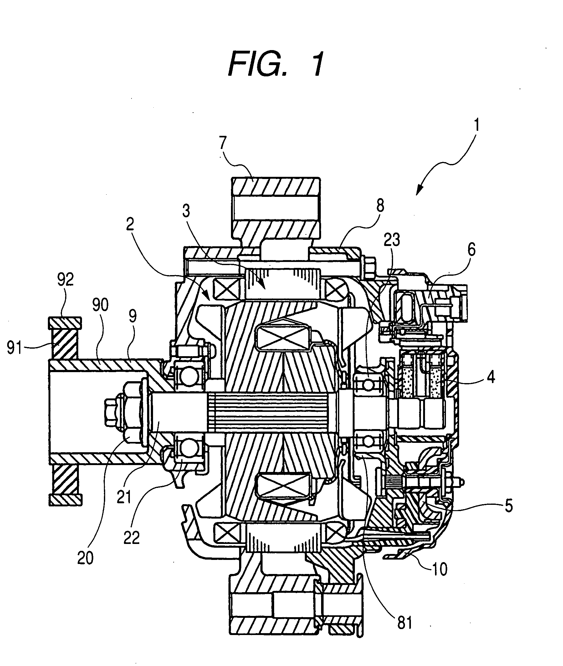
[0025]Referring to the drawings, wherein like reference numbers refer to like parts in several views, particularly to FIG. 1, there is shown an AC generator or alternator 1 for automotive vehicles according to the invention which is illustrated, as an example, as having a cooling fan built therein.

[0026]The alternator 1 consists essentially of a rotor 2, a stator 3, a brush unit 4, a rectifier device 5, an IC regulator 6, a drive frame 7, a rear frame 8, a yoke pulley 9, and a rear cover 10. The rotor 2 has a rotary shaft 21 retained at ends thereof by bearings 22 and 23 to be rotatable.

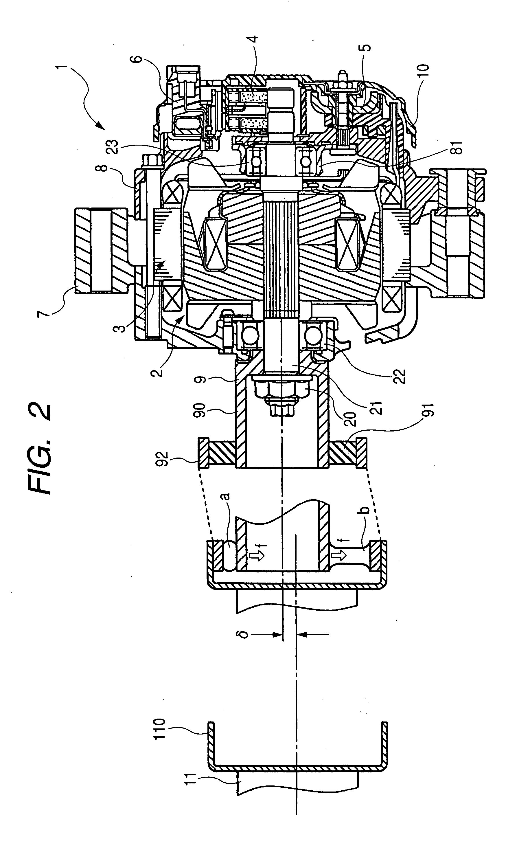
[0027]FIG. 2 is a sectional view which illustrates a joint between a drive shaft 11 and the yoke pulley 9 of the alternator 1. The yoke pulley 9 is made up of a hollow first cylinder 90, a second cylinder 92, and an annular elastic damper 91 made of, for example, rubber. The first cylinder 90 is joined to the shaft 21 of the rotor 2 tightly through a nut 20. The second cylinder 92 is fitted on the pe...


PUM


Abstract

An automotive AC generator is provided which includes a rotary shaft and a generator connector jointed to the rotary shaft. The generator connector is designed to establish a mechanical connection between the rotary shaft and a motor connector joined to a drive shaft of the motor for transmitting the drive torque to the rotary shaft. The generator connector is placed to establish eccentricity between an axis thereof and an axis of the motor connector at all times during rotation of the rotary shaft, thereby resulting in a radial load acting on bearings of the rotary shaft in one direction so as to keep a total load on the bearings greater than zero (0) at all the time. This avoids the seizing of the bearings and creeping of a bearing holder.

Description

CROSS REFERENCE TO RELATED DOCUMENT[0001]The present application claims the benefit of Japanese Patent Application No. 2006-45364 filed on Feb. 22, 2006, the disclosure of which is incorporated herein by reference.BACKGROUND OF THE INVENTION[0002]1. Technical Field of the Invention[0003]The present invention relates generally to an improved structure of an automotive AC generator designed to establish a shaft-to-shaft joint with an engine through, for example, a yoke pulley.[0004]2. Background Art[0005]Typical automotive AC generators or alternators are designed to be supplied with power from the engine to charge a storage battery or feed electric power to an ignition system of the engine, an in-vehicle lighting system, an in-vehicle air conditioner, an audio system, or other electric components. In recent years, an increased number of devices for augment the comfort of the vehicle or devices designed to meet a variety of regulations such as emission regulations have been mounted on...

Claims


Application Information

Patent Timeline
Patent Type & Authority Applications(United States)
IPC IPC(8): F16D3/28H02K7/10H02K5/16
CPCF16D3/76H02K7/003H02K5/1732
Inventor OGI, HIROYUKI
Owner DENSO CORP
Learn More