Vehicle lighting device

a technology for vehicles and lighting devices, applied in lighting and heating devices, lighting support devices, transportation and packaging, etc., can solve the problems of difficult formation of suitable illumination areas for various vehicle driving conditions, pedestrians and oncoming vehicles being a bit dazzled, etc., and achieve the effect of simple configuration

Active Publication Date: 2007-06-28
KOITO MFG CO LTD
View PDF7 Cites 126 Cited by
  • Summary
  • Abstract
  • Description
  • Claims
  • Application Information

AI Technical Summary

Benefits of technology

[0032] By providing a configuration in which each of the light emitting elements of the light source unit includes the LED for emitting light and the optical system for projecting the light emitting surface configuration of the LED so as to project forward the illumination pattern which is similar to the light emitting surface configuration, the LED, which makes up the light source, is strong enough to bear the repetition of being turned on and off and hence can be used over a long period of ti...

Problems solved by technology

Consequently, an elaborate formation of suitable illumination areas for various vehicle driving conditions is difficult.
However, in the event that there are pedestrians an...

Method used


Image

  • Vehicle lighting device
  • Vehicle lighting device
  • Vehicle lighting device

Examples


Embodiment Construction

[0049] Hereinafter, preferred embodiments of a vehicle lighting device according to the invention will be described with reference to the accompanying drawings.

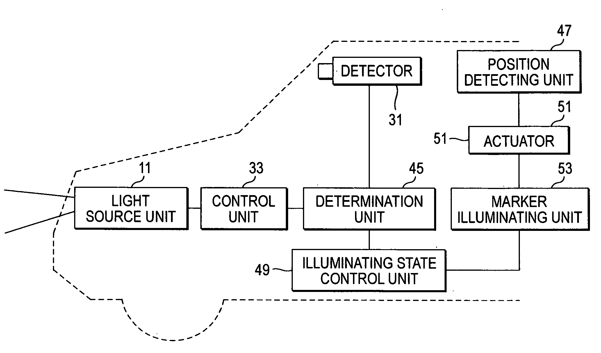
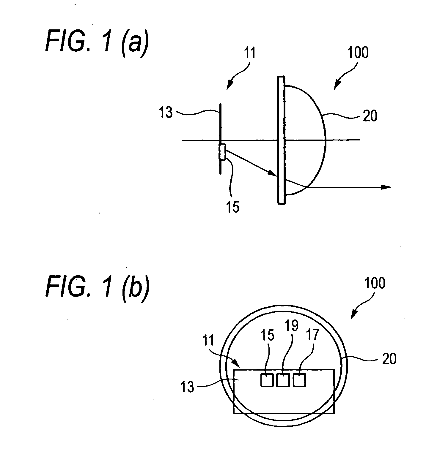
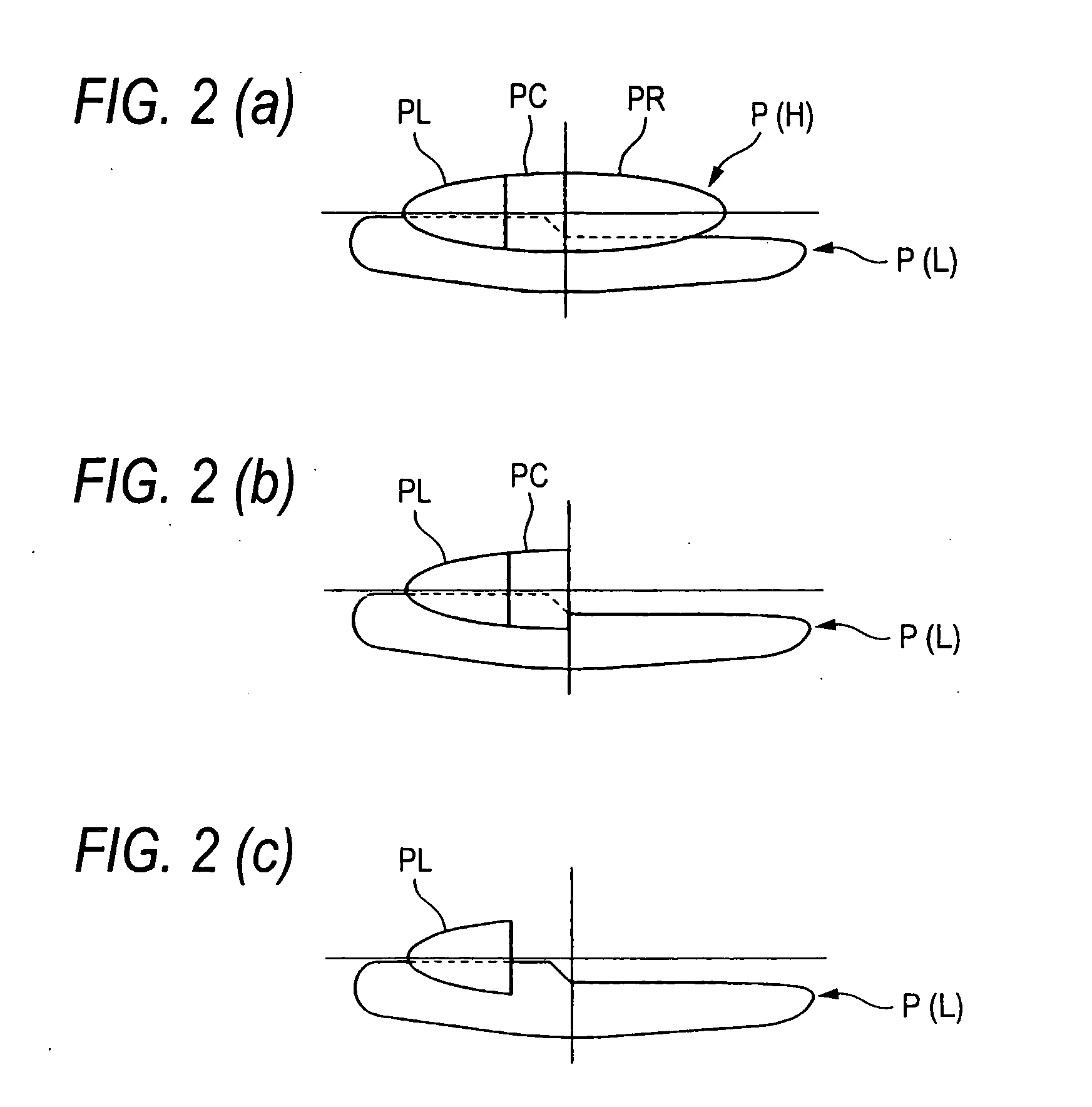
[0050] In FIGS. 1(a) and 1(b), a lighting device in accordance with a preferred embodiment of the present invention is shown. In this embodiment, vehicle lighting device 100 includes a light source unit 11 which emits light and projects forward light from the light source unit 11 to form a high beam light distribution pattern P(H). The high beam light distribution pattern P(H) has at least two illumination patterns which illuminate areas which are different from each other. In this embodiment, an example will be described in which the high beam light distribution pattern has three illumination patterns PL, PC, PR.

[0051] A control unit, which will be described in greater detail below, is connected to the light source unit 11, and the control unit can control individually the illumination patterns PL, PC, PR so as to be turne...


PUM


Abstract

A vehicle lighting device includes a light source unit for emitting light for forming a high beam light distribution pattern by projecting forward light from the light source unit. The high beam light distribution pattern has at least two illumination patterns which illuminate areas which are different from each other. A control unit is provided for controlling the at least two illumination patterns to be turned on and off selectively.

Description

CROSS-REFERENCE TO RELATED APPLICATIONS [0001] This application claims priority to Japanese Patent Application No. 2005-379702, filed Dec. 28, 2005, in the Japanese Patent Office. The priority application is incorporated by reference in its entirety. BACKGROUND OF THE INVENTION [0002] 1. Field of the Invention [0003] The present invention relates to a vehicle lighting device which forms a high beam light distribution pattern by directing light emitted from a light source unit to travel forward, and more particularly to a technique which increases the visibility without dazzling the drivers of a preceding vehicle and an oncoming vehicle. [0004] 2. Description of the Background Art [0005] A projector type lamp unit provided in a headlight which is an automotive lamp typically includes a light source for emitting light, a reflector for reflecting the light from the light source, a projection lens for projecting forward the light reflected by the reflector, a holder which fixes the proj...

Claims


Application Information

Patent Timeline
IPC IPC(8): B60Q1/00F21W107/10
CPCB60Q1/085B60Q2300/056B60Q2300/112B60Q2300/41B60Q2300/42B60Q2300/45F21S41/683F21S41/151
Inventor KOMATSU, MOTOHIRO
Owner KOITO MFG CO LTD
Why Eureka
Try Eureka