Methods for writing non-volatile memories for increased endurance

a non-volatile memory and endurance technology, applied in the field of mass digital data storage systems, can solve the problems of affecting the life of memory cells, affecting the longevity and being subjected to full amount of wear, so as to prolong the lifetime of memory storing such frequently updated data and wear memory cells more quickly

Inactive Publication Date: 2007-06-28
SANDISK TECH LLC
View PDF8 Cites 60 Cited by
  • Summary
  • Abstract
  • Description
  • Claims
  • Application Information

AI Technical Summary

Benefits of technology

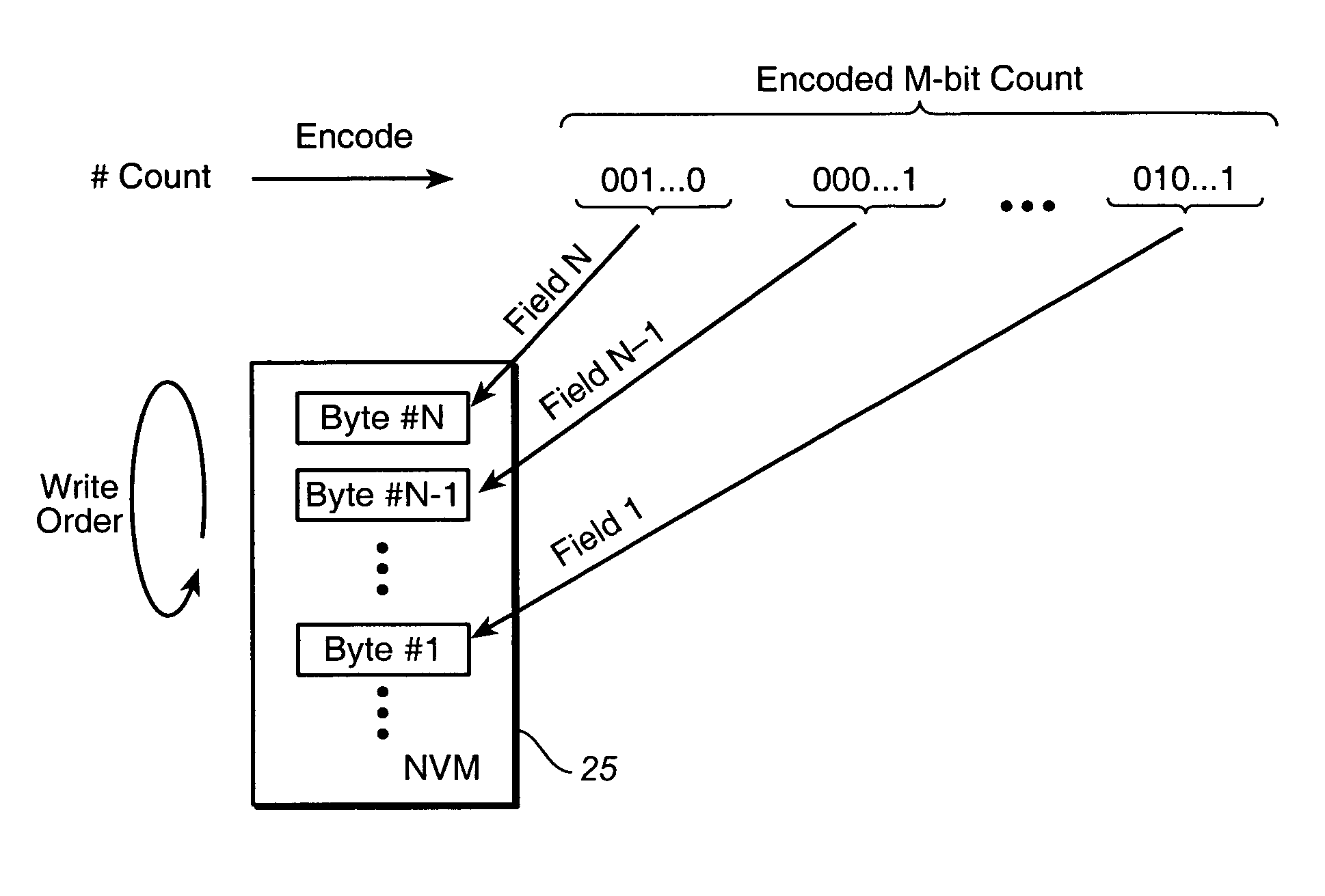
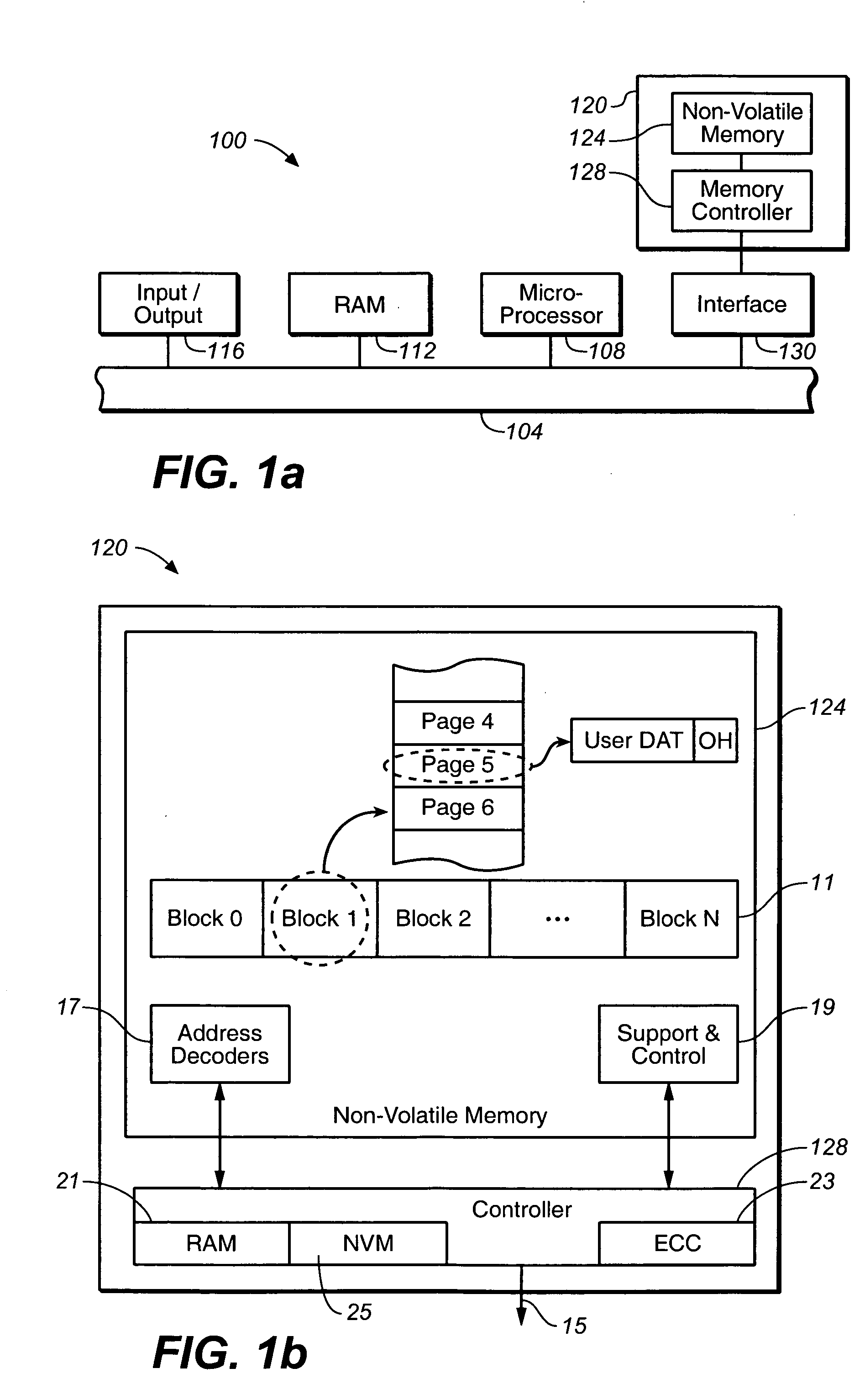
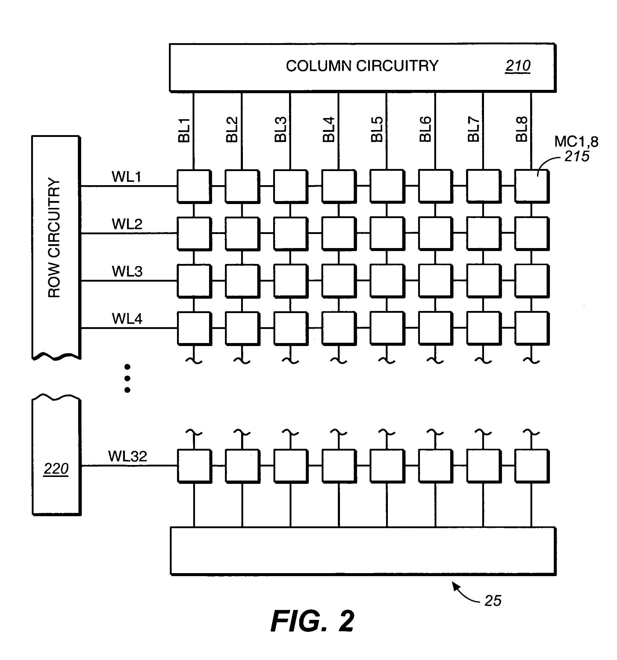
[0010] For example, an exemplary embodiment uses a set of individually accessible byte size memory portions, with each byte (or just a portion of it) is used for each field of the encoded count. Another set of embodiments uses a bit-wise accessible EEPROM memory. The count is then encoded to the individual accessible fields so that as the count is incremented, the rewrites of the fields are evenly distributed. This technique could be used in applications such as a counter for control data maintained in a small non-volatile EEPROM memory formed on the controller of a non-volatile memory system, such as a flash memory card. Such control data is likely to be updated more frequently, and thus wear out memory cells more quickly, than user data stored in the flash memory. By use of the techniques from the present invention, the lifetime for memory storing such frequently updated data can be extended while still using the same technology as the cells used to store user data.

Problems solved by technology

More generally, the memory may be accessed through a larger number of bits, but only those segments that are to be updated are actually rewritten and, consequently, subjected to full amount of wear.
Such control data is likely to be updated more frequently, and thus wear out memory cells more quickly, than user data stored in the flash memory.

Method used


Image

  • Methods for writing non-volatile memories for increased endurance
  • Methods for writing non-volatile memories for increased endurance
  • Methods for writing non-volatile memories for increased endurance

Examples


Embodiment Construction

A. Memory Organization and Basic Definitions

[0017] The present inventions are related to increasing endurance in memory systems that are capable of deteriorating in performance over time as the number of erase and write cycles increases. While the embodiments described herein describe non-volatile EEPROM-based memory systems, the various aspects of the present inventions are applicable to any type of storage medium susceptible to“wear”. For example, an emerging type of non-volatile memory technology is phase-change memory. Information is stored by changing the phase of a given material. A number of other examples of such systems are given in U.S. patent application Ser. No. 10 / 841,379. Such systems also may be prone to“wear”, where the storage medium is less capable of storing information as the number of times the medium has been cycled increases. The present inventions can be readily applied to such technologies.

[0018] In one embodiment, non-volatile memory storage cells within f...


PUM


Abstract

A memory system that incorporates methods of amplifying the lifetime of a counter made up of memory elements, such as EEPROM cells, having finite endurance. A relatively small memory made up of a number of individually accessible write segments, where, depending on the embodiment, each write segment is made up of a single memory cell or a small number of cells (e.g., a byte). A count is encoded so that it is distributed across a number of fields, each associated with one of the write segments, such that as the count is incremented only a single field (or, in the single bit embodiments, occasionally more than one field) is changed and that these changes are evenly distributed across the fields. The changed field is then written to the corresponding segment, while the other write segments are unchanged. Consequently, the number of rewrites to a given write segment is decreased, and the lifetime correspondingly increased, by a factor corresponding to the number of write segments used.

Description

CROSS-REFERENCE TO RELATED APPLICATION [0001] The present application is related to U.S. application Ser. No. ______, of Pinto et al., entitled “System for Writing Non-Volatile Memories for Increased Endurance,” which is filed concurrently with the present application and is hereby incorporated herein, in its entirety, by this reference.BACKGROUND OF THE INVENTION [0002] The present invention relates generally to mass digital data storage systems, and, more particularly, to systems and methods for using memories of limited endurance in situations requiring higher endurance levels. [0003] The use of non-volatile memory systems, such as EEPROM memory or flash memory storage systems is increasing due to the compact physical size of such memory systems, and the ability for non-volatile memory to be repetitively reprogrammed. The compact physical size of flash memory storage systems facilitates the use of such storage systems in devices that are becoming increasingly prevalent. Devices u...

Claims


Application Information

Patent Timeline
IPC IPC(8): G11C8/00
CPCG06F12/0246G06F2212/1036G06F2212/7211G11C8/10G11C16/349G11C16/3495
Inventor PINTO, YOSIGONGWER, GEOFFREY S.HONEN, OREN
Owner SANDISK TECH LLC
Why Eureka
Try Eureka