
Sealing device and rolling bearing device using same

a sealing device and a technology of rolling bearings, applied in the direction of roller bearings, mechanical devices, transportation and packaging, etc., can solve the problems of decreasing the durability of the sealing device, and achieve the effects of maintaining the sealing device for a long time, and increasing the durability of the rolling bearing devi

Inactive Publication Date: 2007-06-28
JTEKT CORP
View PDF6 Cites 36 Cited by
  • Summary
  • Abstract
  • Description
  • Claims
  • Application Information

AI Technical Summary

Benefits of technology

The invention provides a sealing device for a rolling bearing device that can maintain its sealing property over a long period of time while being easily installed onto the device. The sealing device includes a metal core and a seal lip made of elastic material mounted on the metal core in a way that allows for sliding contact with an inner ring of the device. A shielding portion made of elastic material is also mounted on the metal core to prevent the intrusion of muddy water and foreign matters into the clearance between the outer ring and the inner ring. The sealing device can be installed onto the device without adjusting the push amount, making the installation process easier. The shielding portion is formed integrally with the seal lip, simplifying the manufacturing process and reducing production costs. The sealing device prevents the intrusion of muddy water and foreign matters into the interior of the device, increasing its durability and maintaining its sealing property over a long period of time.

Problems solved by technology

Due to this, the sealing device which is fitted in the outer ring 63 on one end side thereof is in a severer condition than a sealing device which is fitted in the outer ring 63 on the other end side thereof, and depending on the running conditions of the vehicle, there has been a risk that the durability of the sealing device is decreased.

Method used


Image

  • Sealing device and rolling bearing device using same
  • Sealing device and rolling bearing device using same
  • Sealing device and rolling bearing device using same

Examples


Embodiment Construction

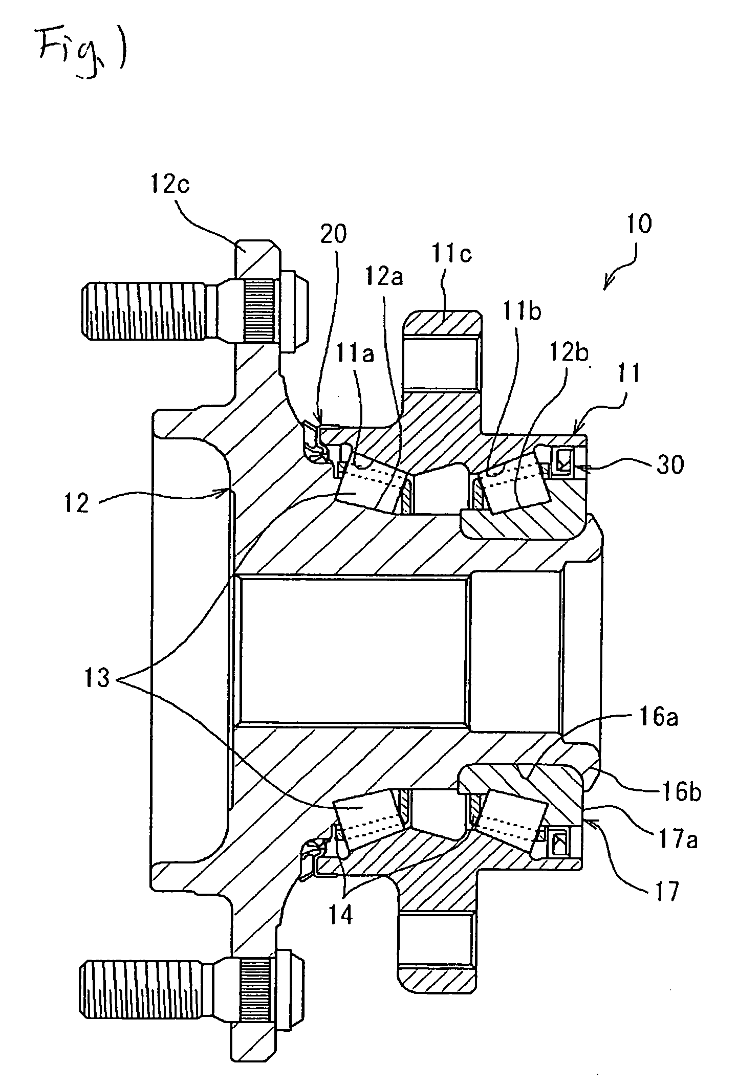
[0019]Next, a preferred embodiment of the invention will be described with reference to the accompanying drawings. FIG. 1 is a sectional view showing a rolling bearing device in which a sealing device according to an embodiment of the invention is used. This rolling bearing device 10 is such as to support rotatably a wheel of a motor vehicle or the like relative to a suspension system of the motor vehicle.

[0020]The rolling bearing device 10 includes an outer ring 11, an inner shaft 12 as an inner ring, a plurality of tapered rollers 13 as rolling elements which are interposed between the outer ring 11 and the inner shaft 12, and cages 14 which hold the tapered rollers separated from each other and makes up a double-row tapered roller bearing device.

[0021]The outer ring 11 is a stationary ring which is fixed to a suspension system of a motor vehicle and has primary and secondary outer ring raceways 11a, 11b which are formed on an inner circumferential surface thereof and a mounting p...


PUM


Abstract

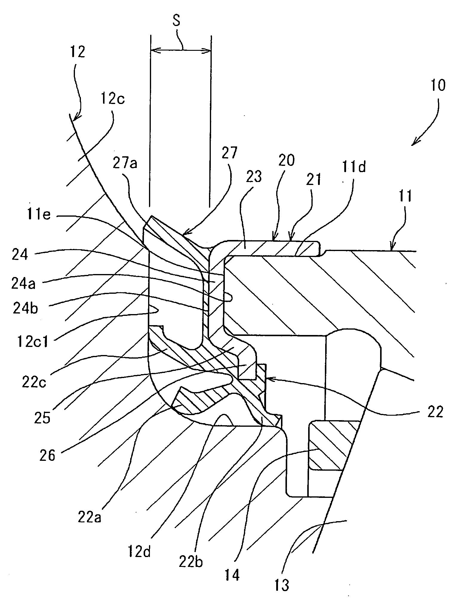
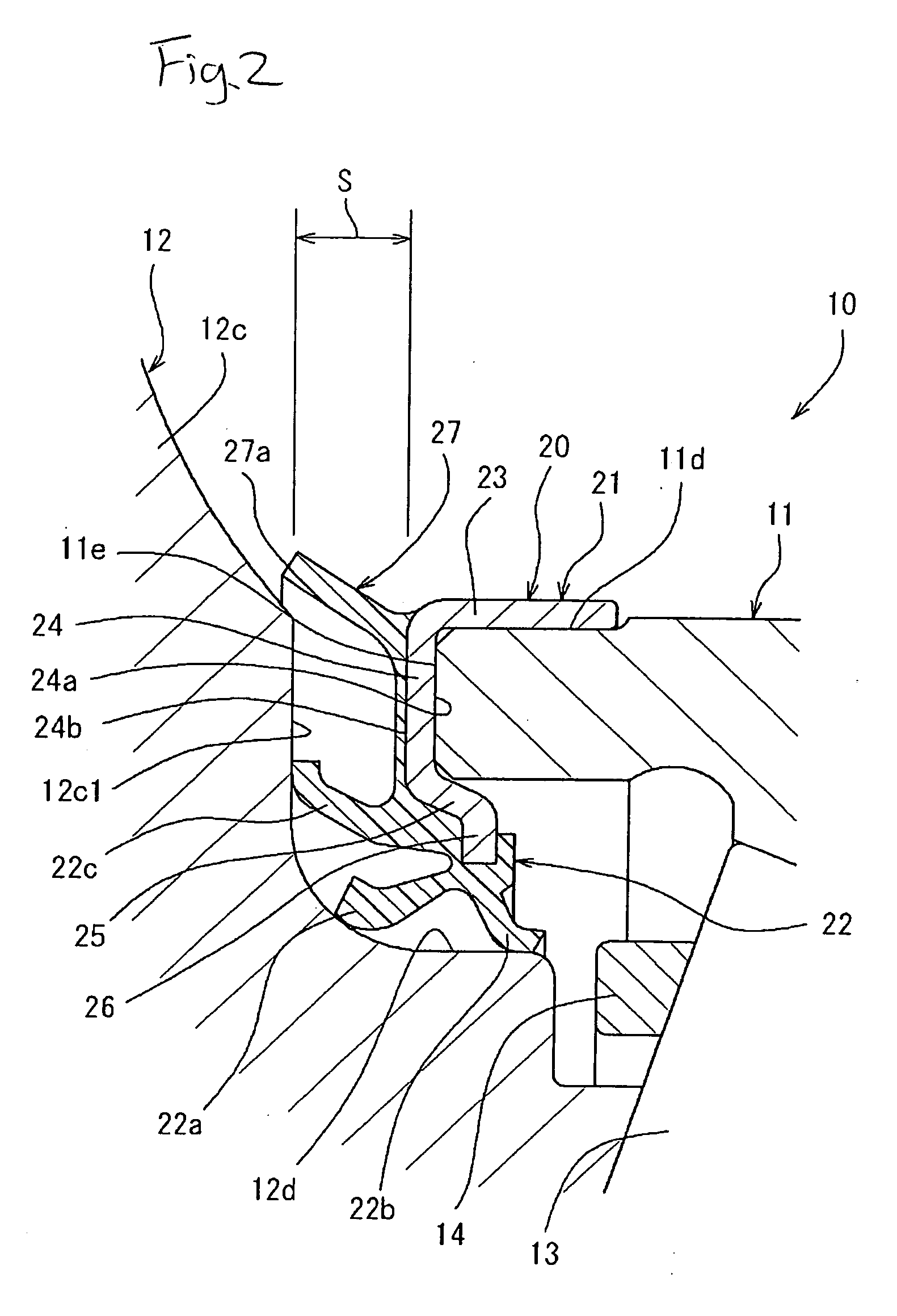
A sealing device for a rolling bearing device includes a metal core which includes a cylindrical portion fitted on an outer circumferential surface of an end portion of an outer ring, a circular ring portion extending radially inwards from the cylindrical portion while being in abutment with an end face of the end portion of the outer ring and an inward edge portion extending further radially inwards from a radially inward end portion of the circular ring portion so as to protrude towards an inner circumferential side of the outer ring and on which seal lips are mounted. A shielding portion made of an elastic material is mounted at a radially outward end portion of the circular ring portion in such a manner as to extend towards a flange portion so as to shield a clearance defined between the flange portion and the end portion of the outer ring.

Description

BACKGROUND OF THE INVENTION[0001]The present invention relates to a sealing device for a rolling bearing device which can maintain its sealing property over a long period of time and a rolling bearing device using the same sealing device.[0002]A sealing device for sealing a clearance between an inner ring and an outer ring of a rolling bearing device has been conventionally used on a rolling bearing device for supporting a wheel of a motor vehicle or the like to prevent the intrusion of muddy water and foreign matters into the interior of the bearing device. The sealing device like this is mounted between the inner ring and the outer ring at both ends thereof (for example, Patent Document No. 1).[0003]FIG. 3 is a sectional view showing a conventional sealing device which is mounted on one end side of an automotive rolling bearing device. In the figure, a rolling bearing device 60 includes an inner ring 62 as a rotating ring on which a flange portion 61 is formed to which a wheel of ...

Claims


Application Information

Patent Timeline
Patent Type & Authority Applications(United States)
IPC IPC(8): F16C33/76B60B35/18F16C19/38F16C33/78F16J15/3232F16J15/3252
CPCF16C19/386F16C2326/02F16C33/805F16C33/7886B60B27/0073F16J15/164F16J15/3232
Inventor TAKIMOTO, MASAO
Owner JTEKT CORP
Learn More