Compound-eye imaging device

a technology of compound eye and imaging device, which is applied in the field of compound eye imaging device, can solve the problems of significant long process time, significant complex process, and problems of known imaging device, and achieve the effects of accurate detection, short time, and simple processing program

Inactive Publication Date: 2007-06-28
FUNAI ELECTRIC CO LTD
View PDF3 Cites 26 Cited by
  • Summary
  • Abstract
  • Description
  • Claims
  • Application Information

AI Technical Summary

Benefits of technology

[0009] An object of the present invention is to provide a compound-eye imaging device having a function to accurately detect, from images imaged thereby, eye positions of a person with a relatively simple processing program in a relatively short time, making it possible to use the detected eye positions for extracting a face area and to perform accurate personal identification based on the extracted face area in a relatively short time.
[0011] This compound-eye imaging device can detect eye positions accurately and in a short time, even using a relatively simple processing program for the eye position detection. This compound-eye imaging device can be used to enable accurate personal identification in a relatively short time.
[0014] Still further preferably, the flash control means controls the flash unit to alternatively emit two kinds of near-infrared lights having different wavelengths while multiple single-eye images are read using the shutter means. This can increase the difference in color (brightness) between the eye areas in the pre-change and post-change single-eye images, so that the eye positions can be detected with improved accuracy.
[0015] The compound-eye imaging device can further comprise: a face extracting means for extracting a face area in the single-eye images based on the eye positions detected by the eye position detecting means in the single-eye images; and a personal identification means for performing personal identification based on the face area extracted by the face extracting means. This compound-eye imaging device enables accurate personal identification in a relatively short time.

Problems solved by technology

However, these known imaging devices have problems.
More specifically, a significantly complex process is required in order to discriminate and recognize red-eye areas of a person present in the image and red circular-shaped areas of e.g. a jewel present in the background of the image.
This causes problems such as a significantly long process time until the detection of the red-eye areas, and a significantly high manufacturing cost of the imaging device itself due to the requirement of a significantly large software (program) to perform the complex process.
Otherwise, if a simple process is used, there is a risk that the red-eye areas cannot be accurately detected, consequently making it unable to accurately extract a face area from the image, thus making the personal identification impossible.
However, since it requires two steps of imaging with and without flash (two-step imaging), it has a disadvantage in that it takes a long time until the red-eye areas are detected.

Method used


Image

  • Compound-eye imaging device
  • Compound-eye imaging device
  • Compound-eye imaging device

Examples


Embodiment Construction

[0023] Embodiments of the invention, as best mode for carrying out the invention, will be described hereinafter with reference to the drawings. It is to be understood that the embodiments herein are not intended as limiting, or encompassing the entire scope of, the invention. Note that like parts are designated by like reference numerals or characters throughout the drawings.

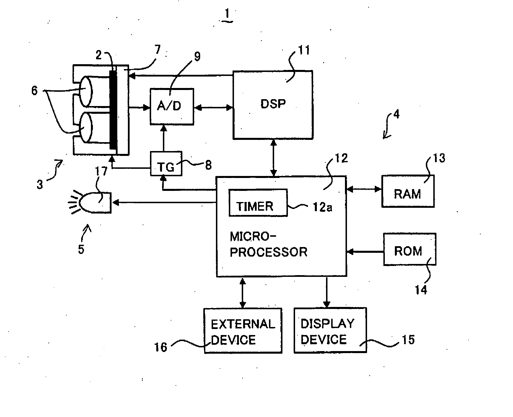
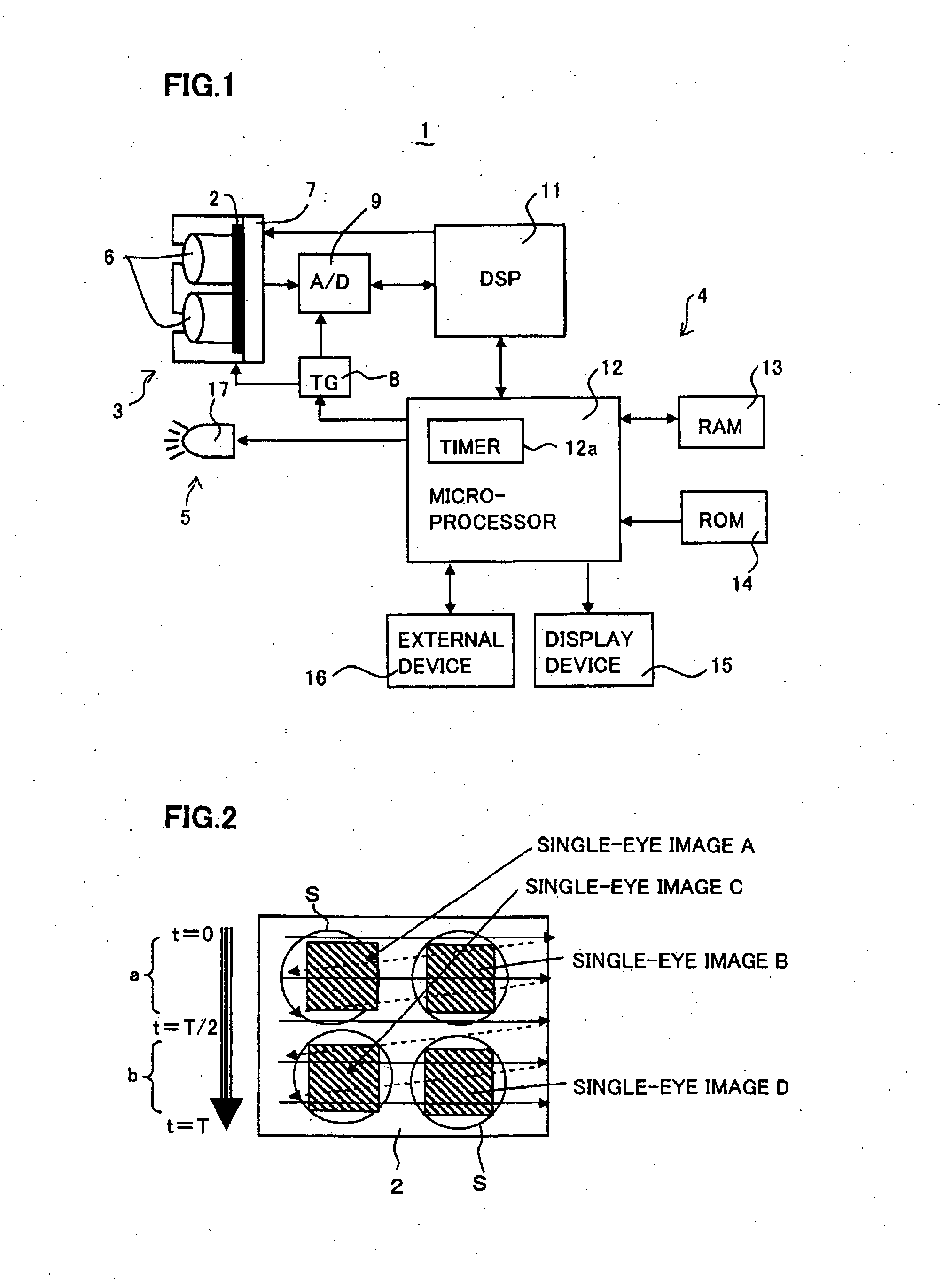
[0024]FIG. 1 is a schematic block diagram of a compound-eye imaging device 1 according to an embodiment of the present invention. The compound-eye imaging device 1 comprises: an optical system section 3 for collecting light from a target object (person) to be imaged to form multiple single-eye images on a solid state imaging element 2; a circuit section 4 for electronically processing the single-eye images imaged by the solid state imaging element 2 to perform personal identification; and a flash unit 5 connected to, and driven or turned on by, the circuit section 4 to emit flash light at a timing described lat...


PUM


Abstract

A compound-eye imaging device comprises a flash control means for controlling a flash unit to alternatively emit two kinds of near-infrared lights having different wavelengths while multiple single-eye images are read using a rolling shutter; a single-eye image reading means for reading, from the single-eye images, a single-eye image (hereafter “pre-change single-eye image”) imaged under a first illumination condition before an illumination condition change by the flash control means, and a single-eye image (hereafter “post-change single-eye image”) imaged under a second illumination condition after the illumination condition change; and an eye position detecting means for detecting eye positions in the single-eye images based on a comparison between the read pre-change and post-change single-eye images. This imaging device can further comprise: a face extracting means for extracting a face area based on the detected eye positions; and a personal identification means for performing personal identification based on the extracted face area.

Description

BACKGROUND OF THE INVENTION [0001] 1. Field of the Invention [0002] The present invention relates to a compound-eye imaging device, and more particularly to a compound-eye imaging device having a function to detect eye positions of a person from images imaged thereby, the detected eye positions being usable to extract a face area from the images to perform personal identification based on the extracted face area. [0003] 2. Description of the Related Art [0004] Imaging devices are known which have a function to recognize a face area contained in an image to perform personal identification. In the field of this kind of devices, Japanese Laid-open Patent Publication 2004-206688 discloses an imaging device to image by intentionally producing a so-called “red-eye” phenomenon, in which eyes of an imaged person are reproduced in red so as to accurately extract a face area. The imaging device. detects the face area based on the red-eye portions in the thus imaged image. [0005] On the other ...

Claims


Application Information

Patent Timeline
Patent Type & Authority Applications(United States)
IPC IPC(8): A61B3/14H04N7/18G03B29/00H04N9/47G06V10/141H04N13/232
CPCA61B3/113A61B5/1176G06K9/00604G06K9/2027H04N5/3532H04N13/0232H04N13/0253H04N13/0296H04N13/232H04N13/254H04N13/296G06V40/19G06V10/141H04N25/531
Inventor NAKAO, YOSHIZUMITOYODA, TAKASHIMASAKI, YASUO
Owner FUNAI ELECTRIC CO LTD
Why Eureka
Try Eureka