Fuel cell water management system and method

a fuel cell and water management technology, applied in the field of fuel cell systems, can solve problems such as difficulty in drawing legibility, channel blockage by water, and unsatisfactory amounts of water, and achieve the effect of improving drawing legibility

Inactive Publication Date: 2007-06-28
FORD MOTOR CO +1
View PDF8 Cites 27 Cited by
  • Summary
  • Abstract
  • Description
  • Claims
  • Application Information

AI Technical Summary

Benefits of technology

[0018] In the drawings, identical reference numbers identify similar elements or acts. The sizes and relative positions of elements in the drawings are not necessarily drawn to scale. For example, the shapes of various elements and angles are not drawn to scale, and some of these elements are

Problems solved by technology

Although some amount of water in the active region of the membrane is desirable, the accumulation of water can result in undesirable amounts of water in some regions of the fuel cell.
If a relatively large amount of water collects in a localized region of a flow field plate channel, however, the channel may become blocked by the water.
In some fuel cell systems, other problems may arise from the accumulation of water in and around the membrane.
Droplets of water may divert gas flow into less-than-optimal patterns over the

Method used


Image

  • Fuel cell water management system and method
  • Fuel cell water management system and method
  • Fuel cell water management system and method

Examples


Embodiment Construction

[0028] In the following description and enclosed drawings, certain specific details are set forth in order to provide a thorough understanding of various embodiments of the invention. One skilled in the art will understand, however, that the invention may be practiced without all of these details. In other instances, well-known structures associated with fuel cell systems have not been shown or described in detail to avoid unnecessarily obscuring descriptions of the embodiments of the invention.

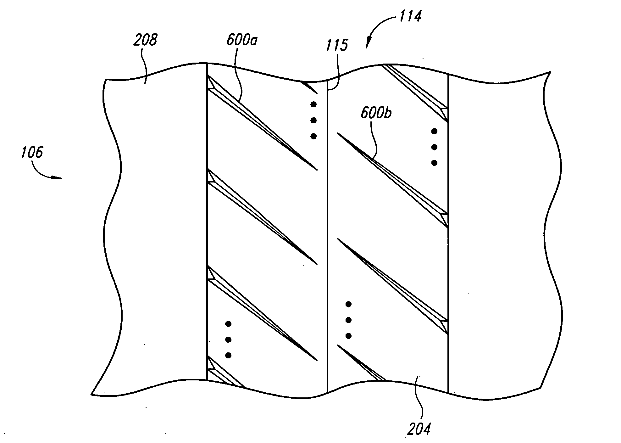
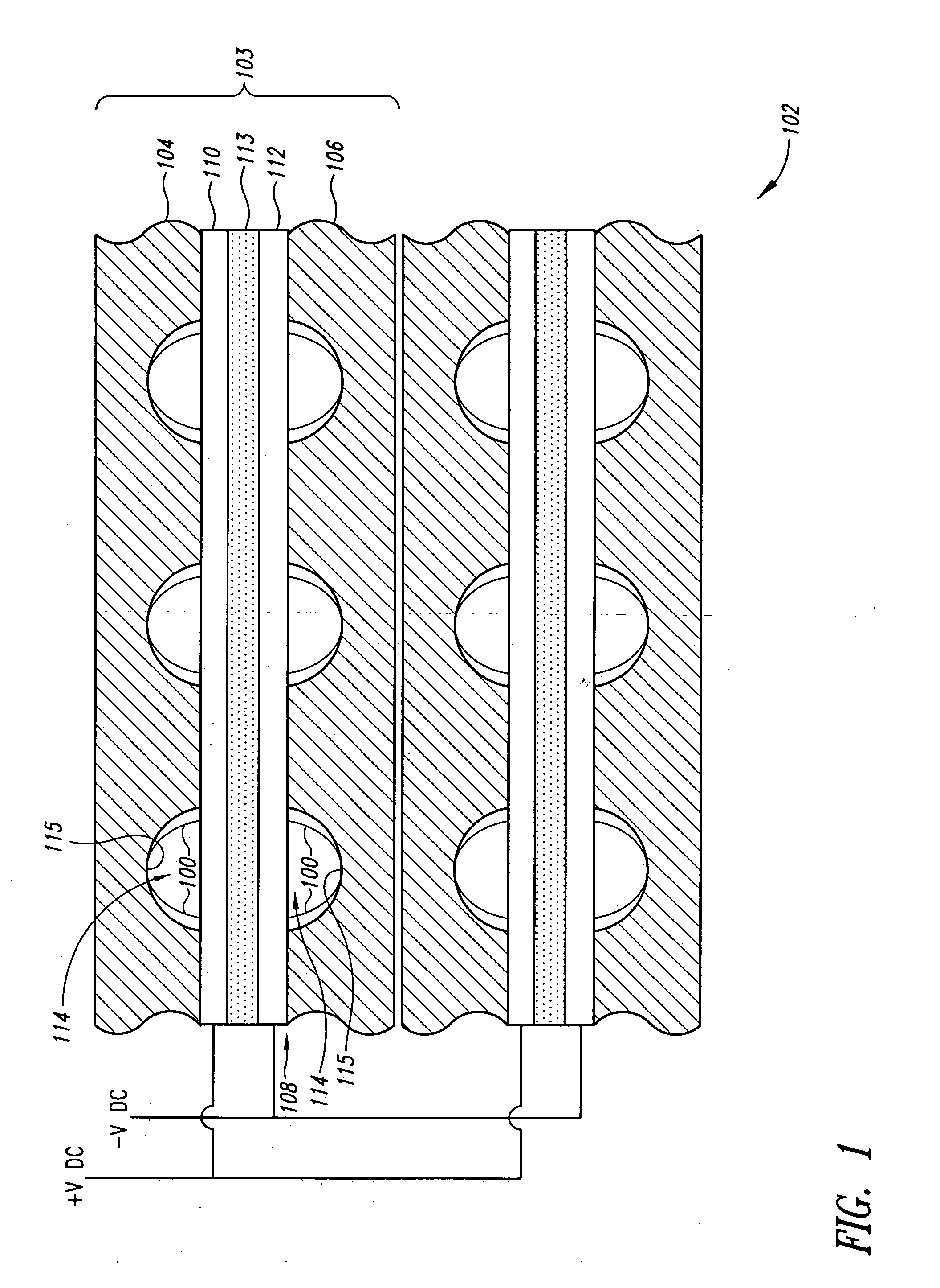
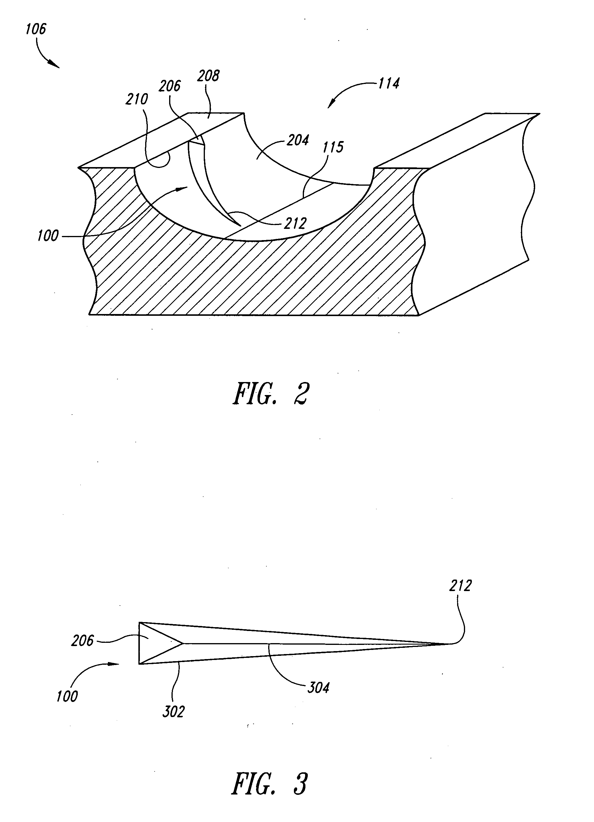
[0029]FIGS. 1-3 illustrate a fuel cell stack 102 having two fuel cells 103, anode and cathode fuel cell flow field plates 104 and 106, respectively, and a pair of membrane electrode assemblies (MEAs) 108. Each MEA 108 includes an anode gas diffusion electrode (GDE) 110, a cathode gas diffusion electrode (GDE) 112 and a membrane 113 therebetween. A plurality of channels 114 in the upper flow field plates 104 provide for the flow of reactant gasses into the anode GDE 110. Similarly, channels i...


PUM


Abstract

Systems and methods for transporting accumulated water in a fuel cell system are disclosed. Briefly described, in one aspect, a system comprises a fuel cell flow field plate with at least one channel disposed on a surface of the fuel cell flow field plate, and at least one water management fin residing on a wall of the channel such that when the accumulated water is transported along the channel the water management fin guides the accumulated water.

Description

BACKGROUND OF THE INVENTION [0001] 1. Field of the Invention [0002] The present invention relates generally to fuel cell systems, and, more particularly, to water management in a fuel cell system. [0003] 2. Description of the Related Art [0004] Electrochemical fuel cells convert reactants, namely fuel and oxidant fluid streams, to generate electric power and reaction products. Electrochemical fuel cells generally employ an electrolyte disposed between two electrodes, namely a cathode and an anode. An electrocatalyst, disposed at the interfaces between the electrolyte and the electrodes, typically induces the desired electrochemical reactions at the electrodes. The location of the electrocatalyst generally defines the electrochemically active area. [0005] One type of electrochemical fuel cell is the proton exchange membrane (PEM) fuel cell. PEM fuel cells generally employ a membrane electrode assembly (MEA) comprising a solid polymer electrolyte or ion-exchange membrane disposed betw...

Claims


Application Information

Patent Timeline
IPC IPC(8): H01M8/02H01M4/94
CPCH01M8/0247H01M8/026H01M8/04156H01M8/04291H01M2008/1095Y02E60/50
Inventor FARRINGTON, SIMONSTARTEK, CARA N.
Owner FORD MOTOR CO
Why Eureka
Try Eureka