Connector

a technology of connecting rods and connectors, applied in the direction of coupling device connection, coupling contact member penetrating/cutting insulation/cable strand, securing/insulating coupling contact members, etc., can solve the problems of increasing the size of the connector, reducing the transmission characteristics of the connector, and difficult to perform connecting operations, etc., to achieve excellent transmission characteristics and facilitate connecting operations

Inactive Publication Date: 2007-06-28
JAPAN AVIATION ELECTRONICS IND LTD
View PDF4 Cites 8 Cited by
  • Summary
  • Abstract
  • Description
  • Claims
  • Application Information

AI Technical Summary

Benefits of technology

[0007] The present invention has been made in view of these problems, and an object thereof is to provide a connector which is excellent in transmission characteristics and at the same time capable of facilitating connecting operations.

Problems solved by technology

In the above-described connector, however, the pitch of the first to third connection portions is only 1.5 times as large as that of the first to third contact portions, and hence the connector suffers from the problem that when cables having a large diameter are used, it is difficult to perform connecting operations.
Although it is possible to increase the pitch of the first to third connection portions by increasing the size of the housing, this undesirably increases the size of the connector.
Further, although it is possible to increase the pitch of the first to third connection portions by arranging the first to third connection portions in two rows on alternately staggered arrangement, this results in degradation of the transmission characteristics of the connector because signal pairs become adjacent to other signal pairs.

Method used


Image

  • Connector
  • Connector
  • Connector

Examples


Embodiment Construction

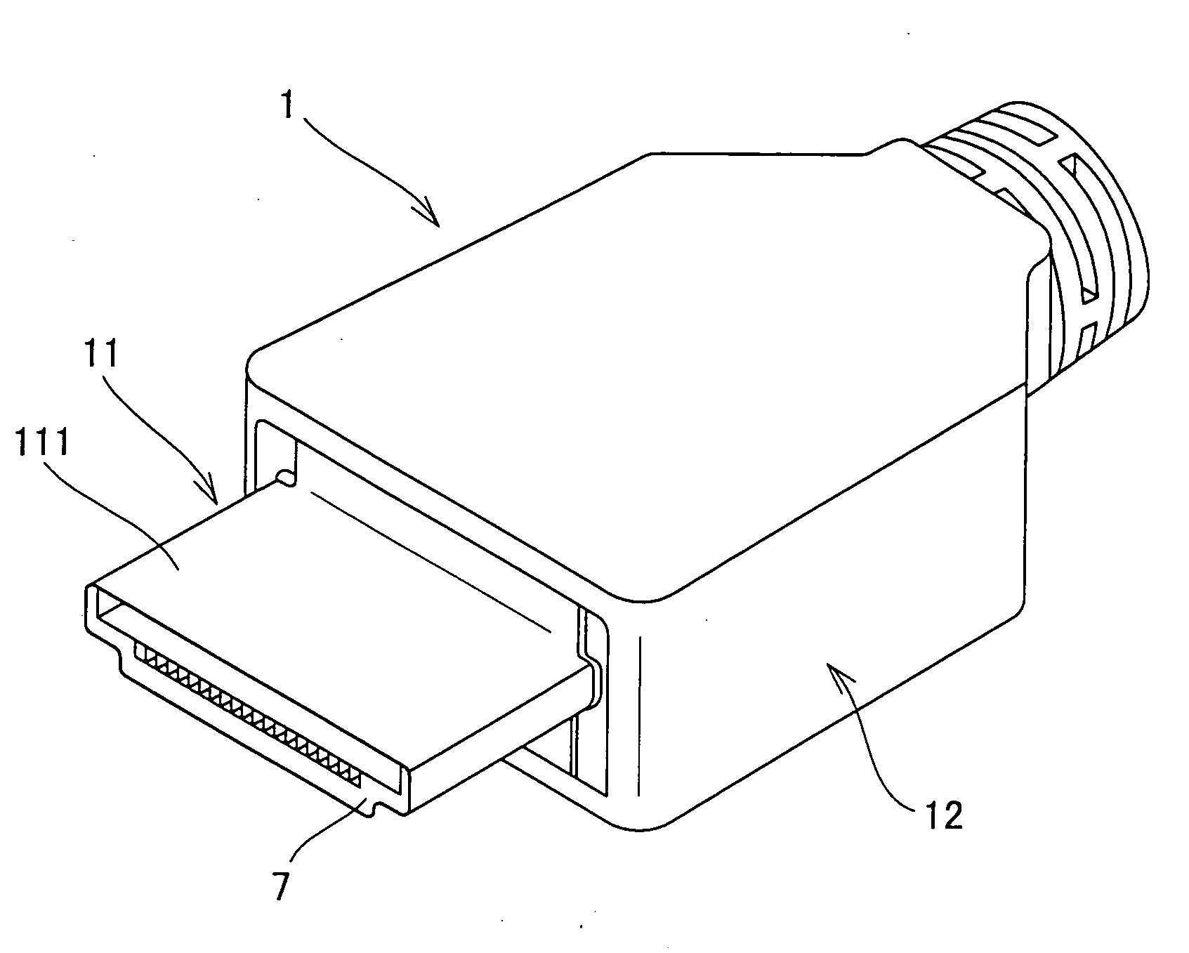
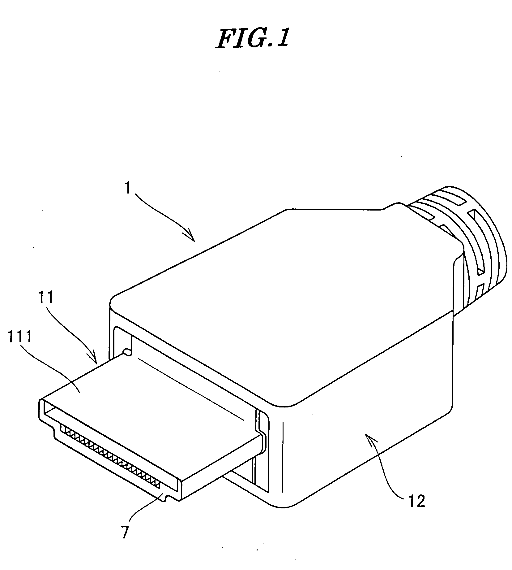
[0033] The present invention will now be described in detail with reference to the drawings showing preferred embodiments thereof.

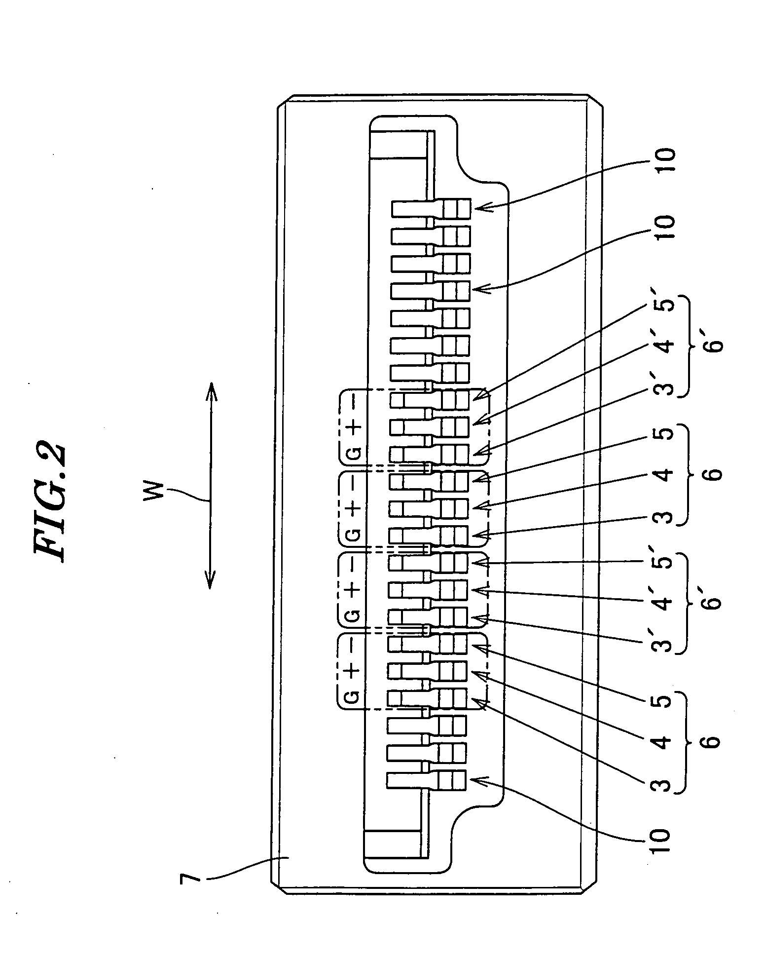
[0034]FIG. 1 is a perspective view of a plug connector according to an embodiment of the present invention. FIG. 2 is a front view of a housing and contacts of the plug connector shown in FIG. 1. FIG. 3 is a plan view of the housing and the contacts shown in FIG. 2. FIG. 4 is a rear view of the housing and contacts shown in FIG. 2. FIG. 5 is a cross-sectional view of the housing and contacts shown in FIG. 2. FIG. 6A is a plan view of ground contacts appearing in FIG. 3. FIG. 6B is a side view of the same. FIG. 7A is a plan view of signal contacts for upper side connection, appearing in FIG. 3. FIG. 7B is a side view of the same. FIG. 8A is a plan view of signal contacts for lower side connection, appearing in FIG. 3. FIG. 8B is a side view of the same. FIG. 9 is a perspective view of the housing appearing in FIG. 2 and a location plate in a state before ...


PUM


Abstract

A connector which is excellent in transmission characteristics and at the same time capable of facilitating cable-connecting operations. One contact group is comprised of a ground contact including a first contact portion and a first connection portion, a first signal contact including a second contact portion and a second connection portion, and a second signal contact including a third contact portion and a third connection portion. A plurality of the contact groups are held by a housing along a direction orthogonal to a connector fitting direction. First to third contact portions of all the contact groups are arranged on a single imaginary straight line substantially orthogonal to the connector fitting direction. The first to third connection portions are arranged such that imaginary straight lines connecting between the first to third connection portions of each contact group form an isosceles triangle, and imaginary straight lines connecting between the first connection portions of all the contact groups form one zigzag line.

Description

BACKGROUND OF THE INVENTION [0001] 1. Field of the Invention [0002] This invention relates to a connector, and more particularly to a connector suitable for high-speed transmission. [0003] 2. Prior Art [0004] Conventionally, there has been proposed a connector which is suitable for high-speed transmission, and is provided with contact groups and a housing (see Japanese Laid-Open Patent Publication (Kokai) No. 2002-334748, Paragraph numbers [0018] and [0019], FIG. 3). [0005] Each of the contact groups is comprised of a ground contact, a positive signal contact, and a negative signal contact. The ground contact has a first contact portion and a first connection portion. The positive signal contact has a second contact portion and a second connection portion. The negative signal contact has a third contact portion and a third connection portion. The contact groups are held in the housing. The first to third contact portions and the first to third connection portions of the contact grou...

Claims


Application Information

Patent Timeline
Patent Type & Authority Applications(United States)
IPC IPC(8): H01R4/24
CPCH01R13/41H01R13/65807H01R23/10H01R23/6873H01R13/6471H01R13/6473H01R24/60H01R24/62H01R24/00
Inventor SAITO, YUICHIOTA, TADAHIRO
Owner JAPAN AVIATION ELECTRONICS IND LTD
Why Eureka
Try Eureka