Wireless communication device

a communication device and wireless technology, applied in the field of wireless communication devices, can solve the problems of difficult for users to tell which devices are connected, time and effort required to input unique parameters, and complicated input methods, so as to achieve the effect of simple operation

Active Publication Date: 2007-06-28
CANON KK
View PDF14 Cites 79 Cited by
  • Summary
  • Abstract
  • Description
  • Claims
  • Application Information

AI Technical Summary

Benefits of technology

[0009] The present invention is directed to overcome the above-described drawbacks and disadvantages. The present invention is, for example, to provide a wireless communication device capable of implementing wireless connection as well as disconnection between desired wireless communication devices using simple operations.

Problems solved by technology

At the same time, however, with wireless communication, since the connection between devices is invisible it becomes difficult for the user to tell which device is connected with which.
In addition, where a plurality of wireless communication devices are present in a range within which wireless communication is possible, although it is possible to use unique parameters such as the IDs or the IP addresses of each device to effect wireless connection, it takes time and effort to input those unique parameters and the input methods are complicated.
In particular, when applying this type of wireless connection method to compact devices such as digital cameras, it is necessary to input these unique parameters using only a few small buttons or keys, which adversely affects user operability.
However, with the method described in Japanese Patent Application Laid-Open No. 2002-118577, where a plurality of other wireless communication devices are within wireless communicable range, it is not easy for the user to know with which device(s) he or she can communicate.
In addition, since the range of radio waves used in wireless communication varies depending on usage conditions and the location of the devices, the user cannot know with certainty the device(s) with which connection has been established.

Method used


Image

  • Wireless communication device
  • Wireless communication device
  • Wireless communication device

Examples


first exemplary embodiment

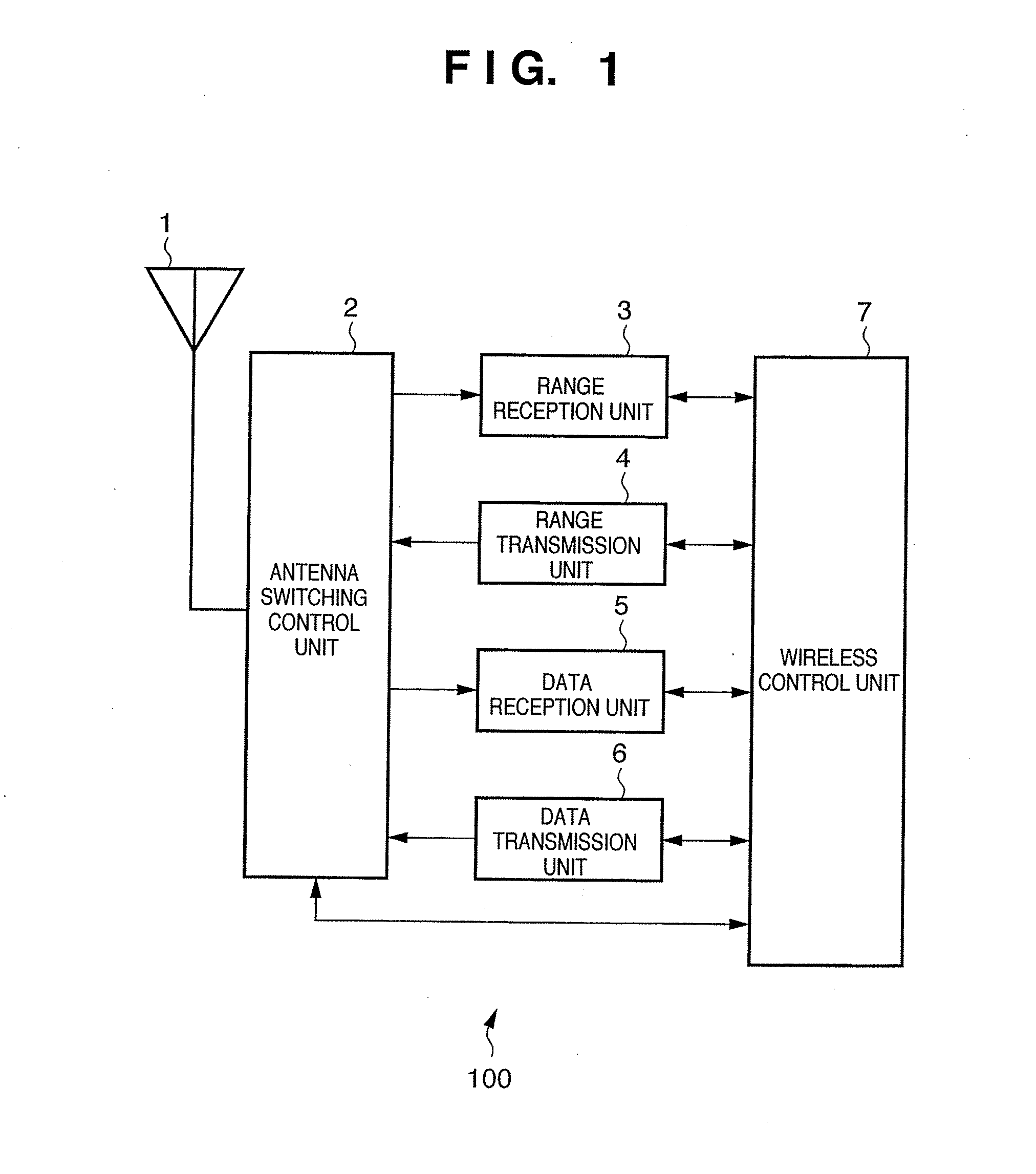
[0028]FIG. 1 is a block diagram showing the main structural components of a wireless communication unit 100 used in a wireless communication device of a first exemplary embodiment of the present invention. The wireless communication unit 100 shown in FIG. 1 may be built into the wireless communication device or it may be removable from the wireless communication device. In addition, a personal computer (PC), printer, digital camera, digital video camera, camera-equipped mobile phone, television receiver or the like can be used as the wireless communication device of the first and other exemplary embodiments.

[0029] The wireless communication unit 100 of the first exemplary embodiment performs wireless communication using a short-range wireless communication method having a ranging function. Although the short-range wireless communication method having a ranging function may be any method, in the first and other exemplary embodiments, UWB (Ultra-Wideband) under consideration by IEEE ...

example 1

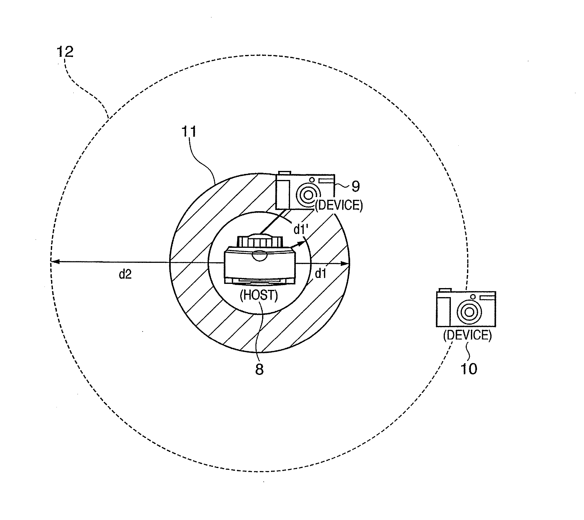
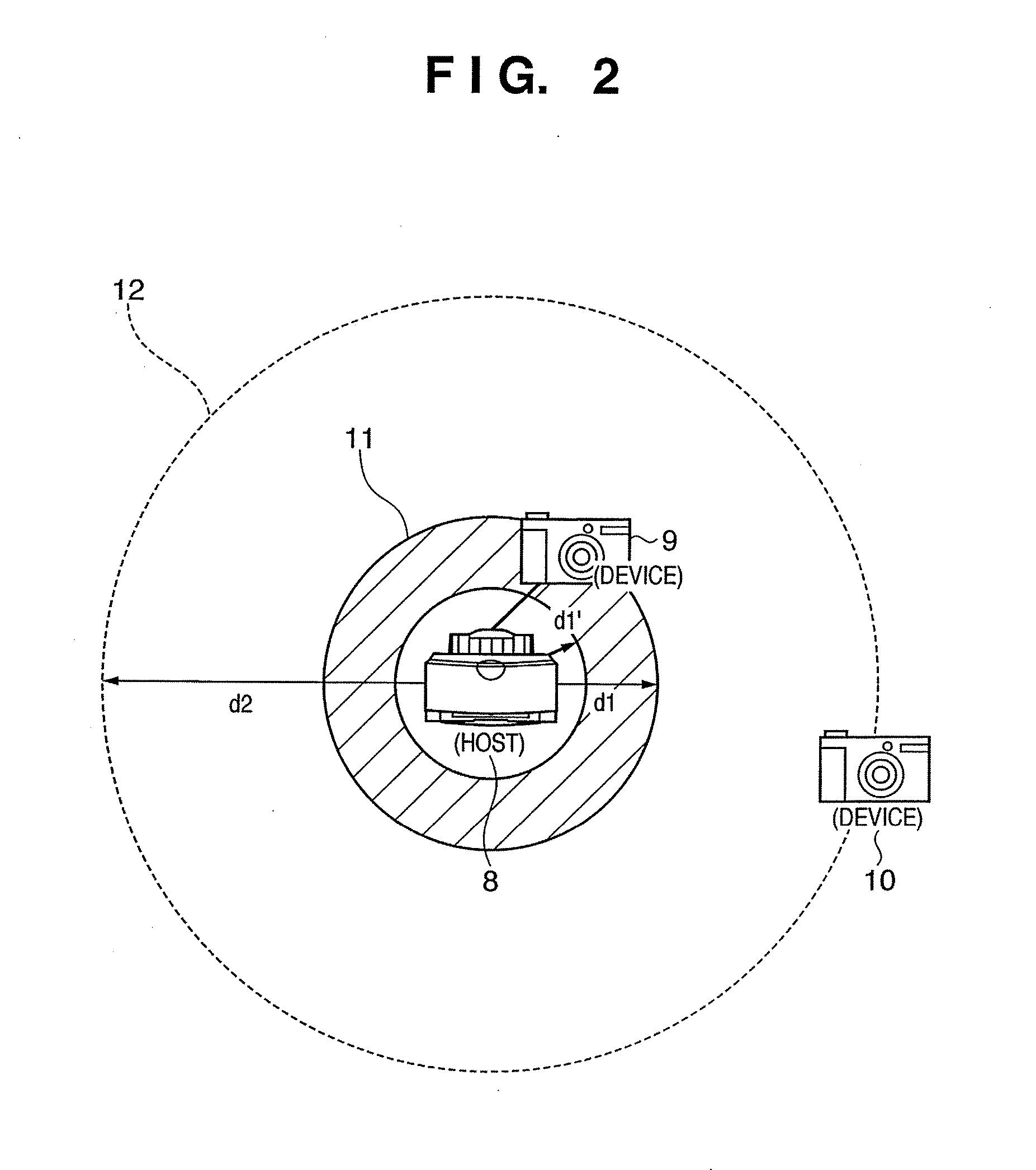
[0063] In a case in which both digital cameras 9, 10, which are capable of wireless communication with the printer 8, are within UWB communicable range 12 of the printer 8 as shown in FIG. 2, the wireless communication unit 100 determines the distances to the digital camera 9 and the digital camera 10 using the UWB ranging function. The UWB ranging function is a ranging function conforming to UWB. The wireless communication unit 100 then compares the distance information received as a result to the UWB connectable area 11 that is set in advance by the user and identifies one of the two digital cameras 9 and 10 as one with which a connection should be established, specifically, effecting a wireless connection with the digital camera that is within the UWB connectable area 11 (in this case, digital camera 9). This can also be called control that establishes wireless connection to the digital camera 9 that is a UWB device that has approached to within a predetermined range that defines...

example 2

[0074] In the Example 2, in a state in which the digital camera 9 has entered the UWB connectable area 11 as shown in FIG. 3, wireless communication is effected if within a predetermined time period (for example, 15 seconds) the digital camera 9 moves closer to the printer 8 by a predetermined distance (for example, 50 centimeters) or more. In other words, a UWB device whose change in distance (approach) is greater than a predetermined amount is identified as a connection.

[0075] In addition, conversely, in a state in which the digital camera 9 is within the UWB connectable area 11, the wireless connection is disconnected if within a predetermined time period (such as 15 seconds) the digital camera 9 moves away from the printer 8 by a predetermined distance (such as 70 centimeters) or more.

[0076] In the Example 2 as well, as with the Example 1, the user can by intuitive operation easily effect a connection to a desired device. Further, in the Example 2, if the change in distance is...


PUM


Abstract

A wireless communication device for effecting wireless communication using a short-range wireless communication method having a ranging function, which carries out wireless connection establishment / disconnection control using ranging information. For example, the wireless communication device determines the range to another wireless communication device within wireless communication range, and if it finds a wireless communication device present within a predetermined range establishes a wireless connection with that wireless communication device, and disconnects the connection if the wireless communication device with which the device is in wireless connection passes beyond a predetermined range.

Description

BACKGROUND OF THE INVENTION [0001] 1. Field of the Invention [0002] The present invention relates to a wireless communication device communicating data via wireless communication. [0003] 2. Description of the Related Art [0004] Within recent advancements in high-speed wireless communication, one technology is known as UWB (Ultra-Wideband). The distinctive features of UWB are short-range high-speed wireless communication and low power consumption. The UWB transfer rate is approximately 10 times greater than the wireless LAN widely used at present, with transmission power on the order of approximately 1 / 30 that of the wireless LAN. [0005] Given these characteristics, UWB is seen as a means for implementing a so-called home network. For example, wireless USB (Universal Serial Bus) is a standard that is aimed at making wireless the current wire communication standard USB using UWB. In addition, since UWB can detect extremely short-duration pulses with high time-accuracy, it has very hig...

Claims


Application Information

Patent Timeline
Patent Type & Authority Applications(United States)
IPC IPC(8): H04B7/00H04B1/38H04B1/3822H04W84/10H04W84/12H04W84/18
CPCH04B5/0062H04B5/02H04W8/005H04W64/00
Inventor ONOZAWA, KATSUYUKI
Owner CANON KK
Why Eureka
Try Eureka