
Antenna system and method for configuring a radiating pattern

Active Publication Date: 2007-06-28
TELECOM ITALIA SPA +1
View PDF13 Cites 119 Cited by
  • Summary
  • Abstract
  • Description
  • Claims
  • Application Information

AI Technical Summary

Benefits of technology

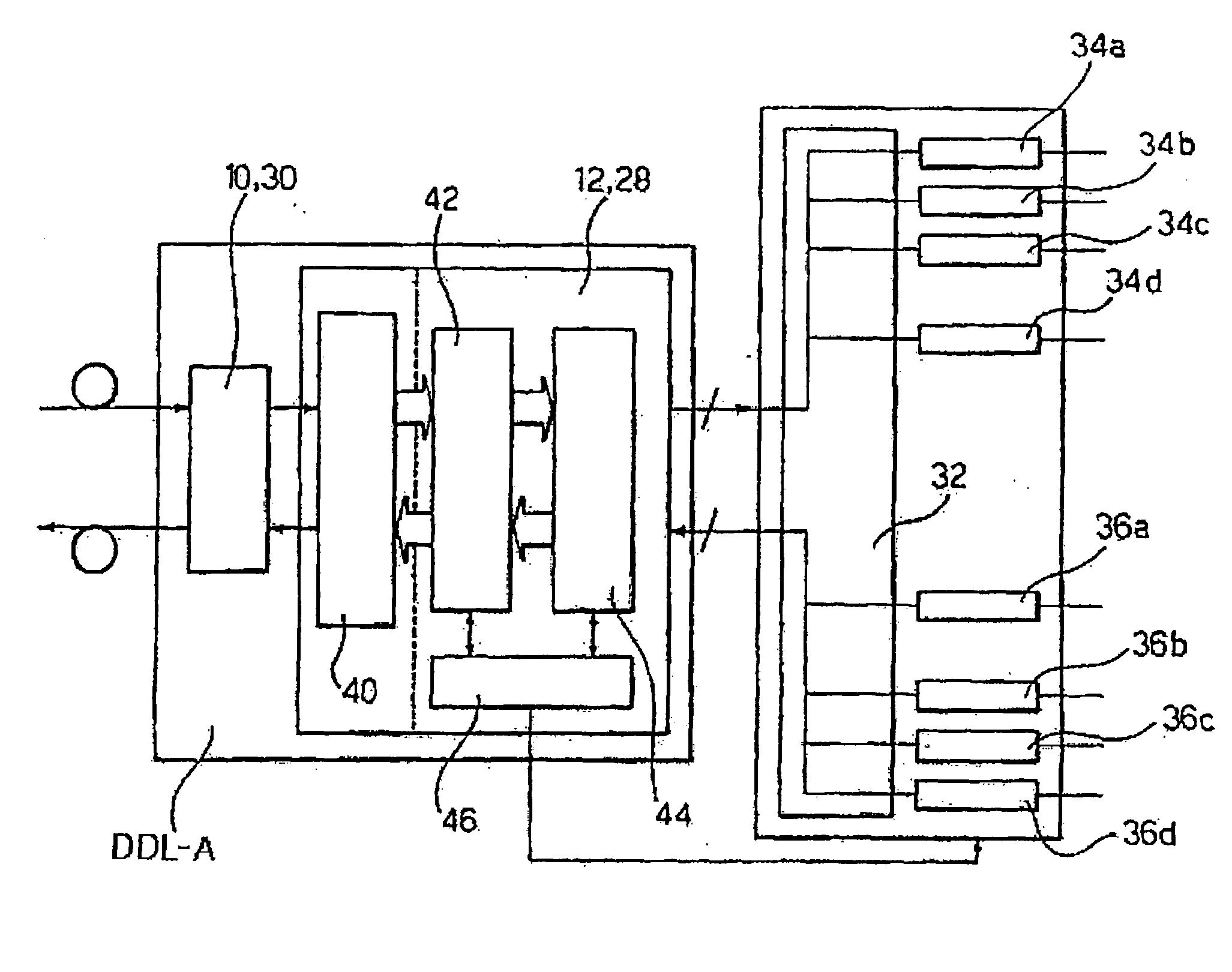
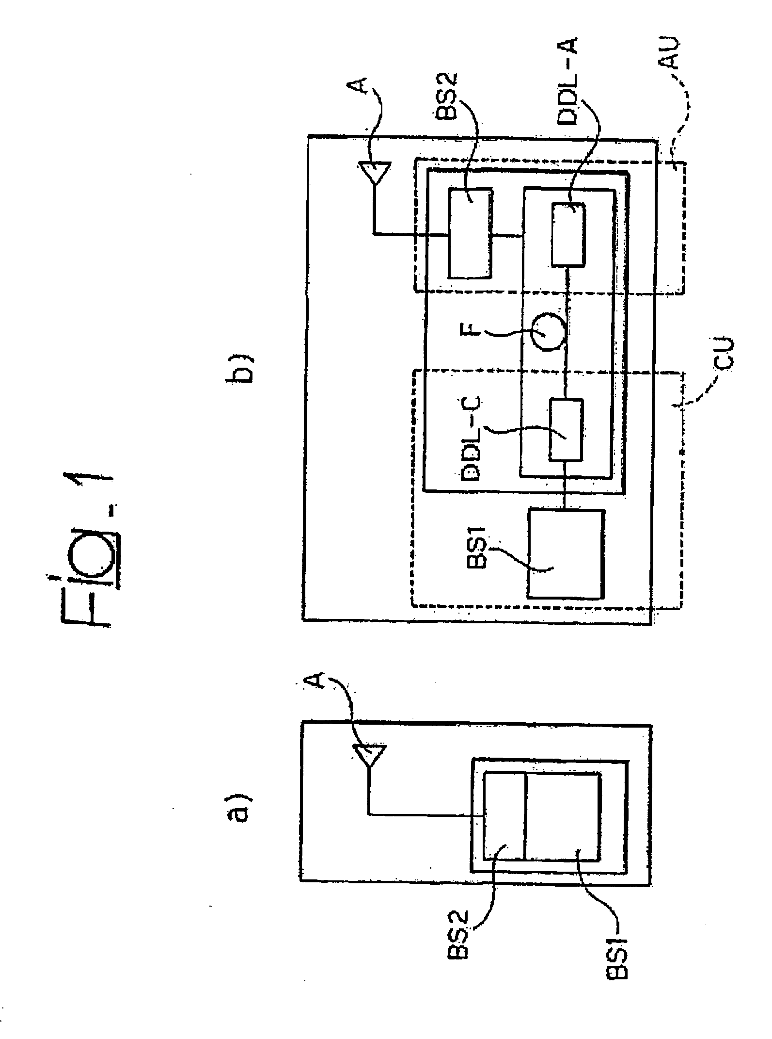
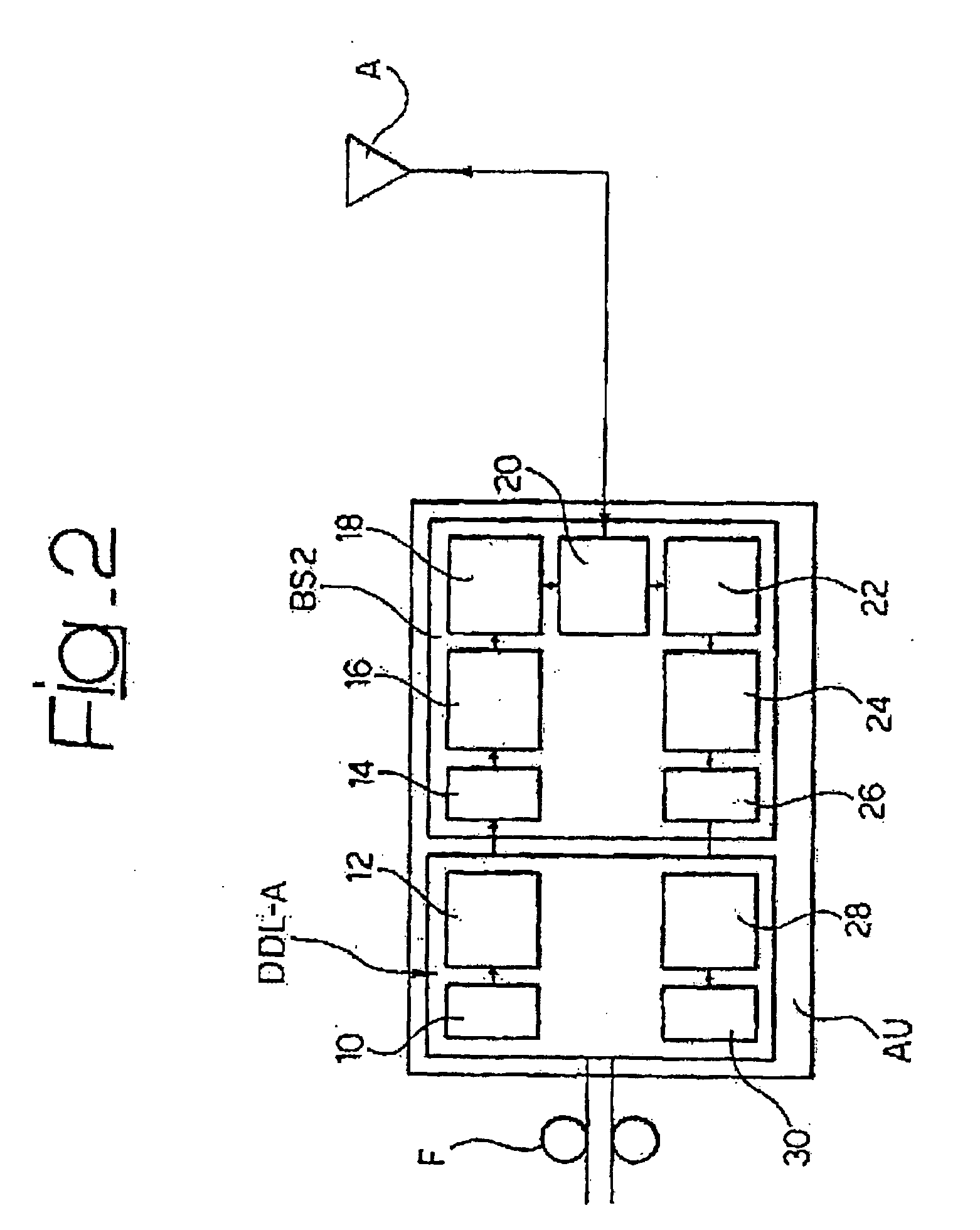
[0029] A particularly preferred embodiment of the solution described herein provides for the presence of devices associated to the antenna (i.e. signal weighting module, antenna conversion set) and of other devices located at some distance and connected to the first devices possibly by means of fibre optic link. In this way it is possible to obtain a communication network, for instance a mobile radio network, which benefits during the planning and operational steps from the ability to modify antenna diagrams according to the needs linked to the variability of traffic conditions over time.
[0031] the information for controlling the antenna beam can be transported through the same link (for instance optical fibre) used to transport the information signal, removing all redundancies in the transport of the signal over optical fibre or cable as instead is the case, as shown for the prior art, if beamforming operations are carried out far from the radiating elements;

Problems solved by technology

A problem of this kind of solution resides in the fact that these antennas normally allow to vary the main lobe direction of the radiation pattern only.
Among the critical issues of this second type of systems, there is the fact that they are prone to failures due to the delicate nature of PIN diodes.
There is also the complexity of construction of such systems and the intrinsic limitation in the degrees of freedom which is typical of PIN diode phase-shifters.
A problem of this type of solution resides in the high bandwidth capacity required from the physical connection between the unit for the digital processing of the signal and the antenna.
The limitation of the prior art system is that the beamforming operation is performed far from the antenna (whether it be passive or active), at appropriate base band signal processing units (positioned for instance at the base of the antenna support tower).
Aside from all other considerations adaptive antenna techniques are normally perceived as rather sophisticated techniques, with a sizeable processing burden associated thereto, both in terms of cost and in terms of the complex and delicate nature of the devices required for their implementation.
Since the requirement to implement adaptability in real time is one of the most difficult specifications to achieve and especially to manage, use of adaptive antennas (sometimes also defined as “adaptive / smart / intelligent antenna systems”) within mobile radio system is, to date, still very unusual and substantially limited to a few sporadic instances.

Method used


Image

  • Antenna system and method for configuring a radiating pattern
  • Antenna system and method for configuring a radiating pattern
  • Antenna system and method for configuring a radiating pattern

Examples


Embodiment Construction

[0038] The detailed description that follows uses as reference general principles of antenna array theory, as presented, for example, in the reference text: [0039] Y. T. Lo, S. W. Lee, Ed., “Antenna handbook—Theory, applications and design”, Van Nostrand Reinhold, New York 1988 (in particular in Chapters 11, 13, 14, 18, 19), and in the literature available to those versed in the art of constructing such antennas.

[0040] Well known synthesis techniques such as, for instance, the techniques known as Dolph-Chebyshev, Taylor, Woodward-Lawson methods can be used to design such antennas. These well known techniques shall not be the subject of a detailed description herein.

[0041] For the purposes of the present description, it will suffice to recall that a configurable remotely controlled antenna is, for example, an antenna in which the setting of the power supply coefficients or weights, applied to each radiating element, is varied operating remotely; in this case this is a concept that ...


PUM


Abstract

The radiation characteristics of an antenna are made configurable including in the antenna a plurality of radiating elements and associating to each of said radiating elements a respective chain for processing the signal in transmission and / or reception with a module for weighting digital signals capable of applying to a digital signal at least a respective weighting coefficient and an antenna conversion set interposed between the module for weighting digital signals and one of the radiating elements of the antenna. The antenna conversion set operates on a digital signal on the side of the signal weighting module and on an analogue signal distributed on the processing chains associated to each radiating element of the antenna propagates (in transmission and / or reception), while respective weight coefficients are applied to said digital signal weighting modules. The weighting coefficients determine the radiation diagram of the antenna.

Description

FIELD OF THE INVENTION [0001] The present invention relates to the techniques that allow to achieve control over the radiation pattern (in transmission and / or reception) of an antenna formed by an array of radiating elements (array antenna). As is well known, such antennas offer the capability of setting nearly any shape for the radiation pattern, provided it is compatible with classic array antenna theory. DESCRIPTION OF THE PRIOR ART [0002] Specific research in the sector and the technological evolution of recent years have allowed to design and build particular radiating systems that are capable of deeply modifying the substantially passive role of traditional antennas used for applications in the field of telecommunications and in particular for the Radio Base Stations (RBS) of mobile communication systems. [0003] In this context, the antenna is the final element of the planning process which, based on a series of design parameters, determines the coverage areas as a function of...

Claims


Application Information

Patent Timeline
IPC IPC(8): H04B1/00H04M1/00H01Q3/26
CPCH01Q3/26H01Q3/2605H01Q3/2676
Inventor CROZZOLI, MAURIZIODISCO, DANIELEGIANOLA, PAOLO
Owner TELECOM ITALIA SPA
Learn More